Film pressure sensitive resistor and pressure sensitive sensor

Inactive Publication Date: 2002-05-14
THE FUJIKURA CABLE WORKS LTD
View PDF12 Cites 80 Cited by
  • Summary
  • Abstract
  • Description
  • Claims
  • Application Information

AI Technical Summary

Problems solved by technology

Therefore, it is difficult for a conventional pressure sensitive sensor to detect a load in the low load range when contact of a upper electrode and a lower electrode starts, and as a result, the measurable load range is not wide.
Furthermore, in the conventional pressure sensitive sensor, since the resistance-load curve is not smooth and has steps as in curve b shown in FIG. 4, the step parts cannot be measured.
Furthermore, in conventional pressure sensitive

Method used


Image

  • Film pressure sensitive resistor and pressure sensitive sensor
  • Film pressure sensitive resistor and pressure sensitive sensor
  • Film pressure sensitive resistor and pressure sensitive sensor

Examples


examples 7 to 12

A film pressure sensitive resistor was prepared using elastic particles composed of nylon 12 having an average particle size (diameter) and content according to each of the Examples and Comparative Examples shown in Table 3. The film pressure sensitive resistor comprises polyester resin as the binder and carbon black as the conductive particles, and the content of the binder and carbon black is 17.5% by volume to the film pressure sensitive resistor. Furthermore, the content of the elastic particles according to each of the Examples and Comparative Examples is shown with a volume ratio of the elastic particles to the film pressure sensitive resistor. The obtained film pressure sensitive resistor was measured with respect to the same properties as described above, and the results are shown in Table 3.

As shown in Table 3, the elastic particles composed of nylon 12 have an average particle size (diameter) of 13 to 20 .mu.m and being 10 to 16% by volume in the film pressure sensitive re...


PUM


Abstract

A film pressure sensitive resistor comprises conductive particles such as carbon black, a binder such as polyester resin, and spherical elastic particles having an average particle diameter of 2 mum to 50 mum, and further has average surface roughness of 0.1 mum to 3 mum, a peak-to-peak concavo-convex period of 10 mum to 1000 mum, and an elastic modulus of 800 MPa to 8000 MPa so as to have reliable quality, and excellent environmental resistance, and durability to repeated use (depressing).

Description

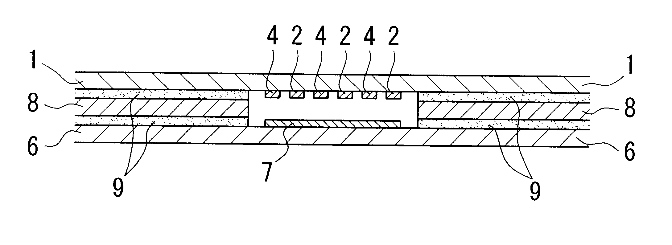
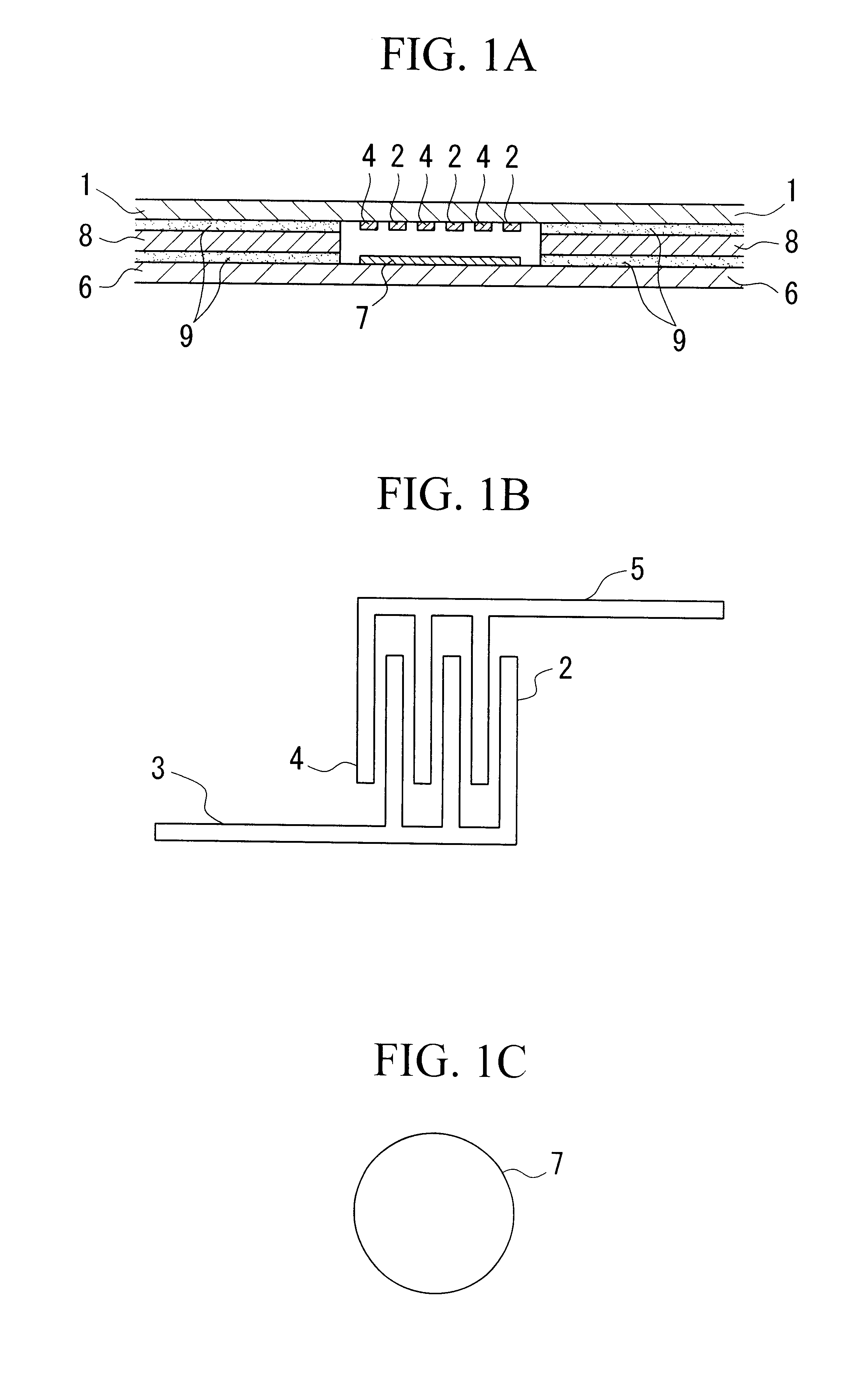
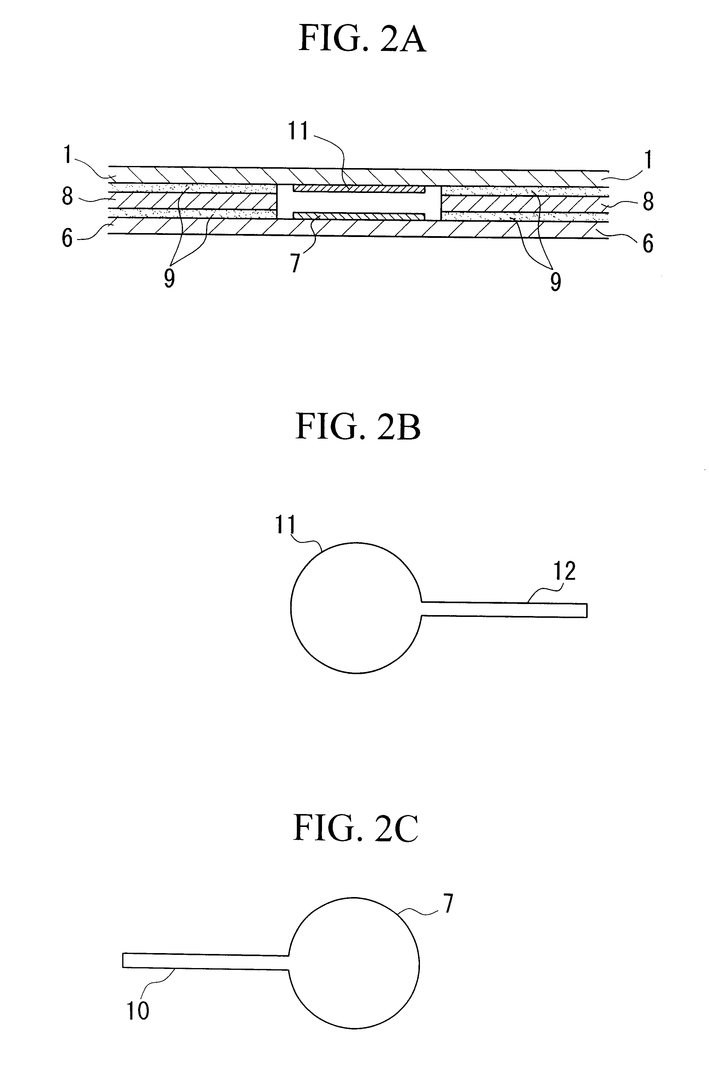
1. Field of the InventionThe present invention relates to a film pressure sensitive resistor in which a resistance value varies according to a pressure, a load, and the like, and to a pressure sensitive sensor made therefrom.2. Description of Related ArtAs a conventional pressure sensitive resistor, for example, a pressure sensitive resistor having a structure as shown in FIGS. 1A to 1C is known. FIG. 1A is a cross sectional view showing an internal structure of a pressure sensitive resistor using three electrodes. FIG. 1B is a plan view showing an electrode pattern and a wiring pattern formed on an upper circuit board in the pressure sensitive sensor shown in FIG. 1A. FIG. 1C is a plan view showing an electrode pattern formed on a lower circuit board in the pressure sensitive sensor shown in FIG. 1A.In the upper circuit board 1 according to this example, an electrode 2 shaped like the teeth of a comb and a wiring part 3 for connecting the electrode 2 and an external device (not sho...

Claims


Application Information

Patent Timeline
IPC IPC(8): H01C10/00H01C10/10G01L1/20
CPCH01C10/106G01L1/20
Inventor IMAI, TAKAYUKINAKAJIMA, TOSHIFUMIISHII, TAKAHIROOCHIAI, TOSHIOKOHAMA, NOBUYUKIHYAKUTAKE, NOBUTADA
Owner THE FUJIKURA CABLE WORKS LTD
Why Eureka
Try Eureka