Low power programmable digital filter

a low-power, filter technology, applied in the direction of pulse manipulation, pulse technique, line-transmission details, etc., can solve the problems of large filter power consumption, and large filter design requirements of many expensive digital multipliers

Inactive Publication Date: 2002-05-14
QUALCOMM INC
View PDF7 Cites 60 Cited by
  • Summary
  • Abstract
  • Description
  • Claims
  • Application Information

AI Technical Summary

Problems solved by technology

The filter design often requires many expensive digital multipliers that consume excess power and occupy valuable circuit board space.
The digital multipliers result in large filter power consumption and decreased mobile transceiver battery life.

Method used


Image

  • Low power programmable digital filter
  • Low power programmable digital filter
  • Low power programmable digital filter

Examples


Embodiment Construction

While the present invention is described herein with reference to illustrative embodiments for particular applications, it should be understood that the invention is not limited thereto. Those having ordinary skill in the art and access to the teachings provided herein will recognize additional modifications, applications, and embodiments within the scope thereof and additional fields in which the present invention would be of significant utility.

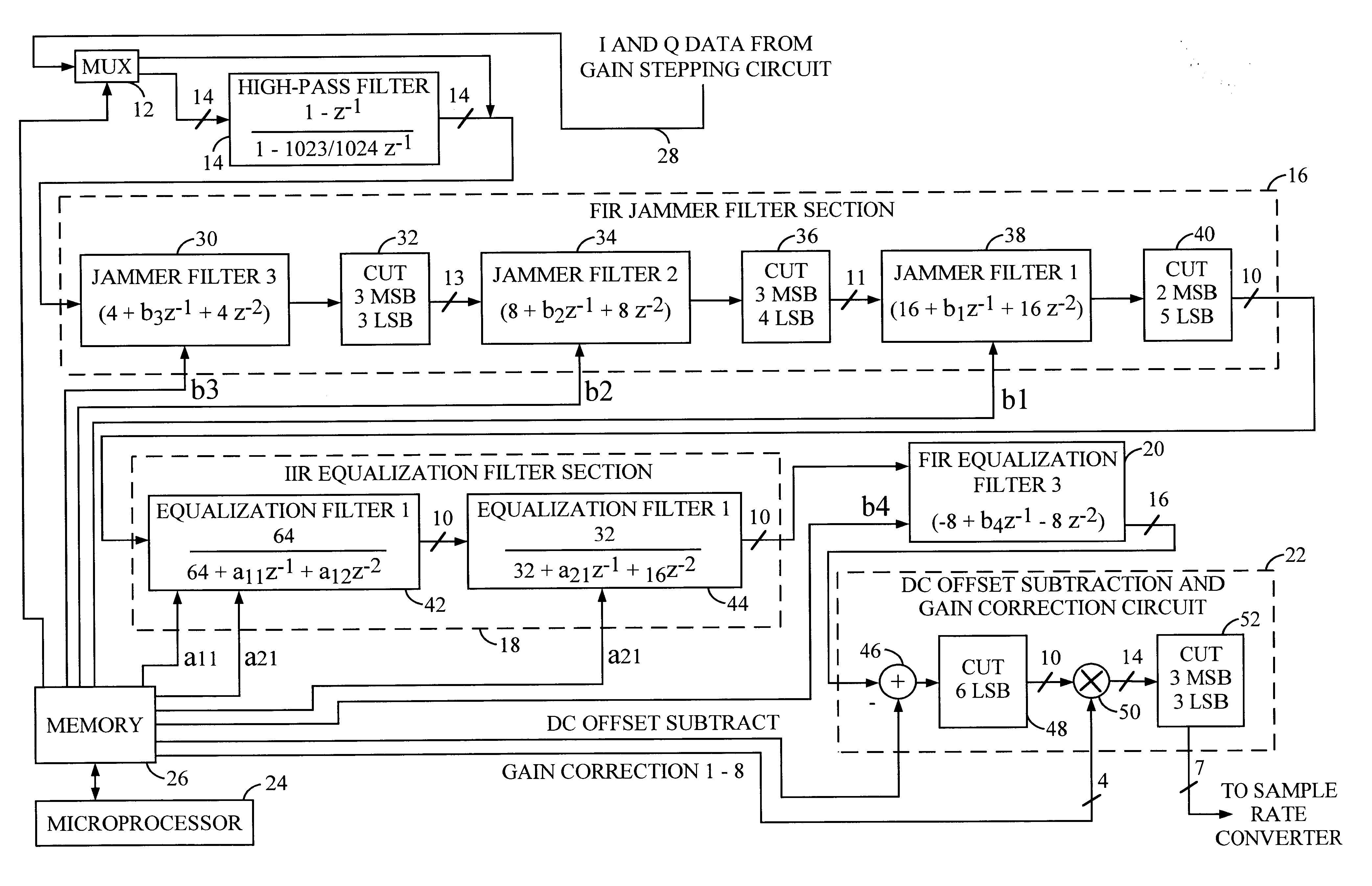
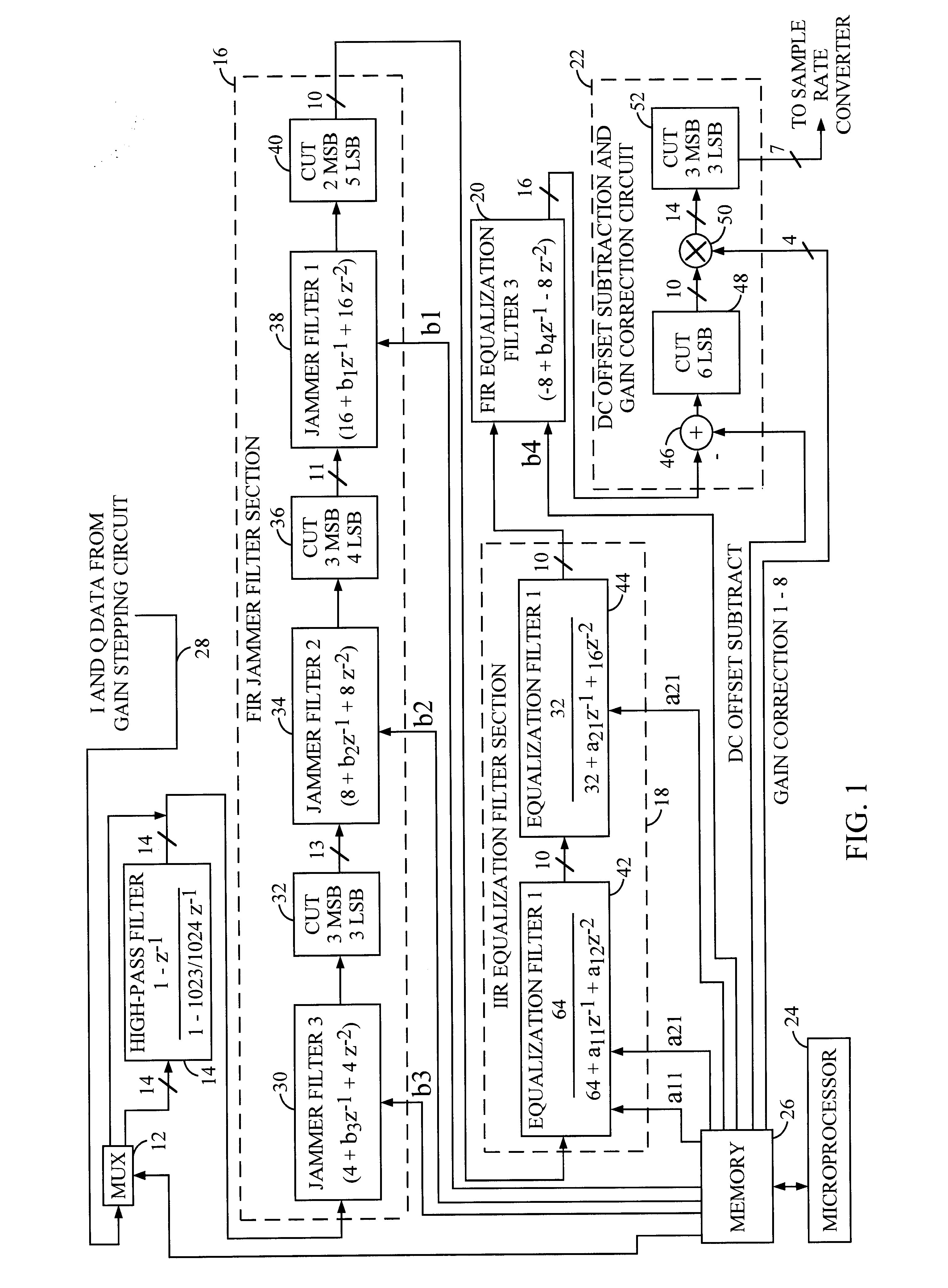
FIG. 1 is a block diagram of a programmable digital filter 10 constructed in accordance with the teachings of the present invention. The programmable digital filter 10 includes an input multiplexer 12, a high-pass filter 14, a finite impulse response (FIR) jammer filter section 16, an infinite impulse response (IIR) equalization filter section 18, an FIR equalization filter 20, and a direct current (DC) offset subtraction and gain correction circuit 22. Various operational parameters of the programmable digital filter 10 are controlled via ...


PUM


Abstract

A low power programmable digital filter adapted for use with a telecommunications system transceiver. The digital filter includes a first finite impulse response filter section for receiving an input signal and having a first transfer function. An infinite impulse response filter section is connected to the first finite impulse response filter section and has a second transfer function. A second finite impulse response filter section is connected to the infinite impulse response filter section and outputs a filtered output signal in response the receipt of the input signal by the programmable digital filter. The second finite impulse response filter section has a third transfer function. A programmable coefficient is included in the first, second, and / or the third transfer function. In a specific embodiment, the first transfer function has a first programmable coefficient. The second transfer function has a second programmable coefficient and the third transfer function has a third programmable coefficient. The programmable digital filter further includes a processor for providing a control signal. A memory provides the first, second, and / or third programmable coefficients in response to the control signal. A high-pass filter section provides input to the first finite impulse response filter section. A multiplexer selectively bypasses the high-pass filter in response to a bypass control signal from the processor. The processor generates the bypass control signal in response to bias occurring in the input signal. In the illustrative embodiment, the first finite impulse response filter section includes a first jammer filter, a second jammer filter, and a third jammer filter for removing telecommunications jammer signals in the input signal. The first, second, and third jammer filters have first, second, and third jammer filter transfer functions with the first programmable coefficient, a fourth programmable coefficient, and a fifth programmable coefficient, respectively. The infinite impulse response filter section includes a first equalization filter and a second equalization filter.

Description

1. Field of InventionThis invention relates to digital circuits. Specifically, the present invention relates to programmable digital filters for use in telecommunications systems.2. Description of the Related ArtDigital filters are used in a variety of demanding applications ranging from electronic control systems to cellular telecommunications systems. Such applications often require programmable digital filters that consume minimal power.Digital filter programmability and low power consumption are particularly important in digital cellular telecommunications systems such as code division multiple access (CDMA) systems. A typical CDMA cellular telecommunications system is characterized by a plurality of mobile transceivers in communication with one or more base stations. Signals transmitted by the mobile transceivers are received by a base station and often relayed to a mobile switching center (MSC). The MSC in turn routes the signal to another base station, a public switched telep...

Claims


Application Information

Patent Timeline
Patent Type & Authority Patents(United States)
IPC IPC(8): H03H17/02H03H17/06H03H17/04H04B3/06H04B7/005H04B7/26
CPCH03H17/0294H03H17/0288H03H17/0291H03H17/0227
Inventor MATHE, LENNART
Owner QUALCOMM INC
Why Eureka
Try Eureka