Filter and method of filtering a fluid

a filter and fluid technology, applied in the field of filters, can solve the problems of reducing the flow rate capability of the filter, affecting the efficiency of the filter, and the fluid passing through the filter medium is difficult to achieve, so as to reduce the pressure drop through the filter, increase the filtration capacity, and reduce the effect of fluid passing through the filter

Inactive Publication Date: 2002-05-21
3M INNOVATIVE PROPERTIES CO
View PDF50 Cites 91 Cited by
  • Summary
  • Abstract
  • Description
  • Claims
  • Application Information

AI Technical Summary

Benefits of technology

Filters of the type disclosed herein demonstrate superior fluid distribution over the filter medium contained therein, and an optimum use of the filter medium. Filters according to the present disclosure, therefore, have an increased life and a lower pressure drop without a reduction in filter rating, and provide more cost effective filtering.
The advantageous performance described above for Test Cartridges 3 and 4 is confirmed by visual inspection. Upon dissection of the Test Cartridge 3 after testing, the filter medium 16 displayed contaminant loading to a radial depth from the outermost layer 24 of about fifty percent (50%) of the filter 14. In comparison, only the outermost layer of filter medium displayed contaminant loading in Test Cartridge 1. Thus, the combination of the diffusion medium 20 and the bypass apertures 18 as described for Test Cartridges 3 and provides a synergetic effect that was not to be expected based upon the performances of Test Cartridges 1 and 2 possessing either non-filtering diffusion medium or bypass apertures, respectively, but not both.

Problems solved by technology

When a depth filter cartridge mimics a surface filter and collects contaminants in primarily one layer, the results are an inefficient distribution of fluid over the filter medium, a higher pressure drop for fluid passing through the filter and a lower flow rate capability for the filter.
Such filters also tend to have a shorter useful life, and thus must be replaced more often.
The Drori filter elements fail to optimally enhance fluid flow while providing extended filter service life.

Method used


Image

  • Filter and method of filtering a fluid
  • Filter and method of filtering a fluid
  • Filter and method of filtering a fluid

Examples


example i

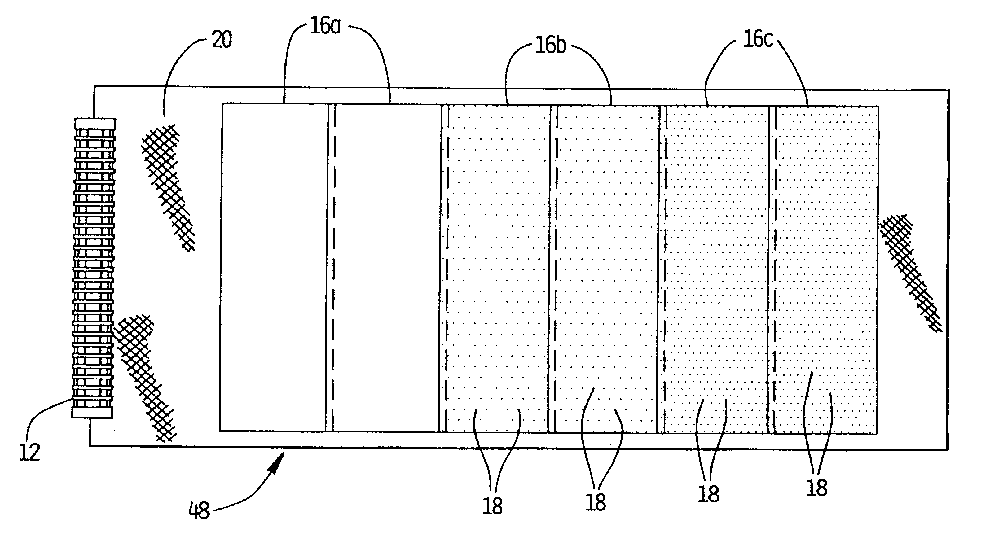
Referring to FIG. 7, an exemplary filter 48 according to the present disclosure is shown. The filter 48 includes a single continuous sheet of diffusion medium 20 comprising thirty thousandths of an inch (30 mils), bi-planar strand orientation (17 mil strand size), twelve strands per inch, polypropylene extruded netting. The Side-to-Height Ratio of such diffusion medium is approximately 4:1. The filter material, which comprises melt-blown, non woven polypropylene micro fibers, is provided in a plurality of discrete sheets 16a, 16b, 16c. The plurality of sheets of filter medium 16a, 16b, 16c exhibit substantially equal and consistent pore size and fiber geometries. As shown, the ends of the sheets 16a, 16b, 16c are overlapped. The overlapping ends of the sheets 16a, 16b, 16c, however, are not sealed or bonded since the tightly wound sheet of the diffusion material 20 provides an adequate seal between the overlapping ends of filter medium.

Inner (with respect to the core 12) sheets 16a ...

example ii

Referring to FIG. 8, a second example of a filter 50 according to the present disclosure is shown. The filter 50 includes a single continuous sheet of diffusion medium 20 comprising thirty thousandths of an inch (30 mils), bi-planar strand orientation (17 mil strand size), twelve strands per inch, polypropylene extruded netting. The Side-to-Height Ratio of the diffusion medium 20 is approximately 4:1. The filter material, which comprises melt-blown, non woven polypropylene micro fibers, is provided in a plurality of discrete sheets 16a, 16b, 16c, 16d.

The sheets of filter medium 16a, 16b, 16c exhibit substantially equal and consistent pore size and fiber geormetry. Sheet 16a does not have bypass apertures, while outer sheets 16b, 16c have bypass apertures 18. The outermost sheet 16c of filter material is preferably provided with more numerous bypass apertures 18 than the intermediate sheets 16b. Most preferably, the sheets 16b, 16c are perforated in a manner substantially similar to ...

example iii

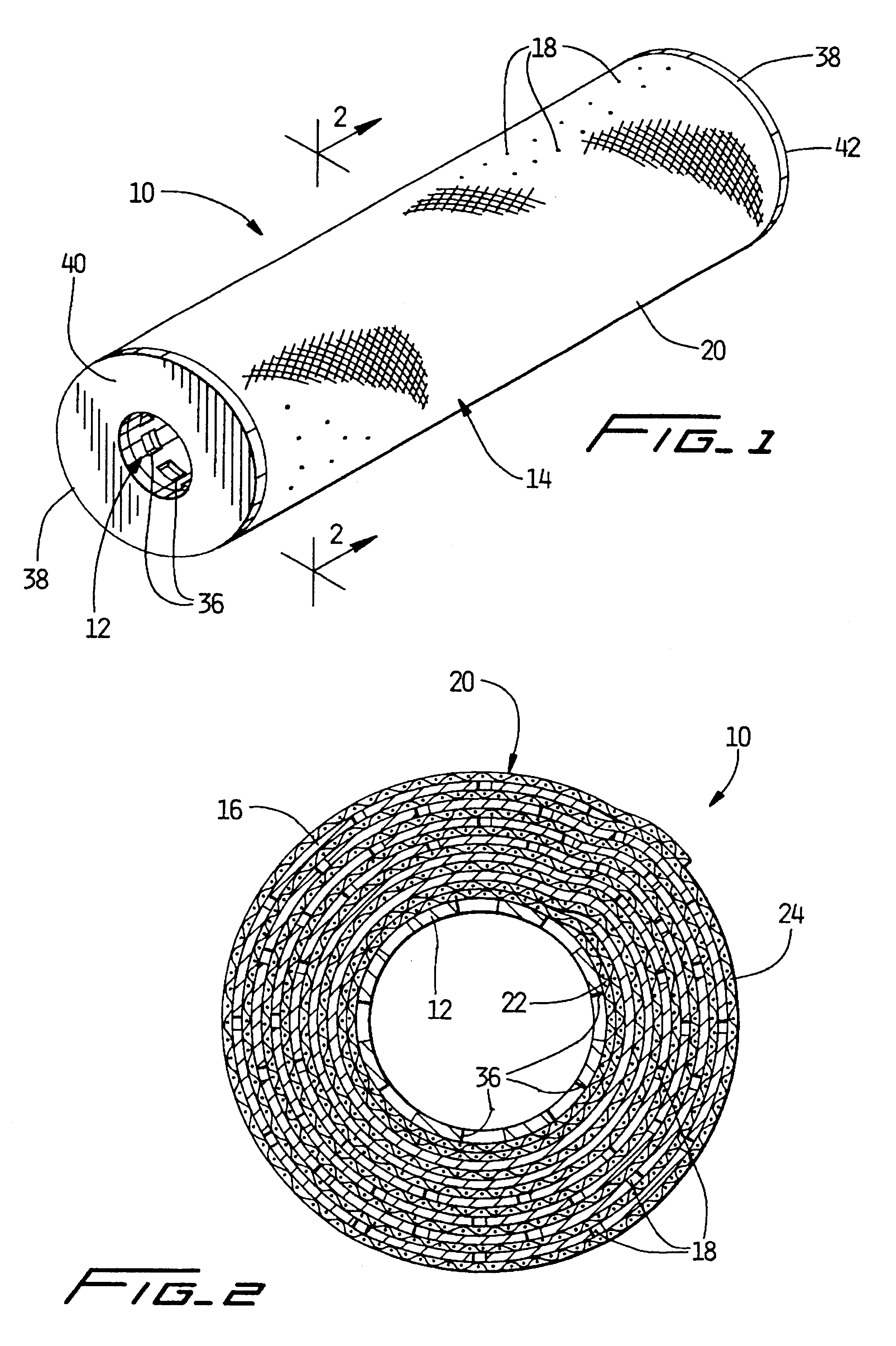
Referring to FIG. 9, another filter cartridge 70 according to the present disclosure is shown. The filter cartridge 70 is similar to the filter cartridge 10 of FIG. 7, and elements that are the same have the same reference numerals. The filter cartridge 70 includes a filter 72 having alternating layers of filter medium 74 and diffusion medium 76.

The filter medium 74 has bypass apertures provided therein and aligned with one another so as to form radial from bores 78 extending from an outermost layer 80 towards an innermost layer 82 of the filter. The radial bores 78 each extend to a uniform depth within the filter 72. Preferably, the bores 78 extend radially to between about fifty and eighty-five percent (50%-85%) of the radial distance from the outermost layer 80 to the innermost layer 82 of the filter 72. More preferably, each of the bypass bores 78 extends radially to about sixty-six percent (66%) of such radial distance. It should be noted that the filter medium of the filter ca...


PUM

PropertyMeasurementUnit
temperatureaaaaaaaaaa
thicknessaaaaaaaaaa
outer diameteraaaaaaaaaa

Abstract

A spiral wound filter element is disclosed which includes alternating layers of filter medium and diffusion medium wrapped about a cylindrical core defining a central axis of the filter element. The alternating layers extend from a radially innermost layer of the filter element to a radially outermost layer of the filter element, the diffusion medium is defined by a continuous lengthwise sheet of mesh material, and the filter medium is defined by at least one sheet of filter material arranged along the length of the continuous sheet of mesh material. The alternating layers of filter medium and diffusion medium define three distinct radially disposed layered filtering sections surrounding the cylindrical core, and include a first filtering section having radially outer prequalifying layers, a second filtering section having middle prequalifying layers and a third filtering section having radially inner qualifying layers. The radially outer prequalifying layers and the middle prequalifying layers define about two-thirds of the radial distance from the radially outermost layer of the filter element to the radially innermost layer of the filter element.

Description

BACKGROUND OF THE DISCLOSURE1. Technical FieldThe present disclosure relates, in general, to a filter, a method of making a filter and a method of filtering a fluid.More particularly, the present disclosure relates to a filter having alternating layers of non-filtering diffusion medium and filter medium. Some of the layers of the filter medium are provided with bypass apertures, while the remaining layers do not include bypass apertures so that they act as qualifying layers for the filter. Filters according to the present disclosure have been found to provide improved fluid distribution over the filter medium, reduced pressure drop and increased filter life, without a reduction in filter rating.2. Discussion of Background DisclosuresIn general, a filter assembly is used for removing contaminants from fluids, i.e., liquids or gases. Such filter assemblies, for example, are used in chemical and hydrocarbon applications such as polyethylene manufacturing, food and beverage applications...

Claims


Application Information

Patent Timeline
Patent Type & Authority Patents(United States)
IPC IPC(8): B01D39/18B01D39/16B01D39/08B01D69/12B01D69/00B01D63/06B01D25/24B01D29/11B01D25/00
CPCB01D25/24B01D29/111B01D39/083B01D39/086B01D39/1623B01D39/1692B01D39/18B01D63/06B01D69/12B01D29/216B01D2239/1291B01D2239/0618B01D2239/0622B01D2239/0627B01D2239/065B01D2239/0654B01D2239/0663B01D2239/0668B01D2239/069B01D2239/0695B01D63/103
Inventor PULEK, JOHN L.HAMLIN, THOMAS J.SALE, RICHARDPAUL, C. THOMAS
Owner 3M INNOVATIVE PROPERTIES CO
Why Eureka
Try Eureka