Circularly polarized wave antenna and device using the same

a technology of circular polarization and antenna, which is applied in the structural form of the antenna, the structure of the radiating element, and the support/mounting of the antenna, etc., can solve the problems of increasing the size of the antenna, difficult to adjust and set the interval between the respective resonance frequency in the fundamental and higher modes, and complex structure of the antenna 30

Inactive Publication Date: 2002-05-21
MURATA MFG CO LTD
View PDF6 Cites 13 Cited by
  • Summary
  • Abstract
  • Description
  • Claims
  • Application Information

AI Technical Summary

Problems solved by technology

On the other hand, there arise the problems that the size of the antenna is increased, since the dielectric substrate 37 is overlaid on the dielectric substrate 33 so as to form plural steps.
With this configuration, problematically, the structure of the antenna 30 becomes complicated.
Furthermore, problematically, it is difficult to adjust and set the interval between the respective resonance frequencies in the fundamental and higher modes.
Accordingly, in the case of the circuit provided on the back face of the circuit substrate as described above, it is difficult to electrically connect the feed pins and the circuit to each other sufficiently, and moreover, there is the problem that patterning the circuit is difficult.

Method used


Image

  • Circularly polarized wave antenna and device using the same
  • Circularly polarized wave antenna and device using the same
  • Circularly polarized wave antenna and device using the same

Examples


first embodiment

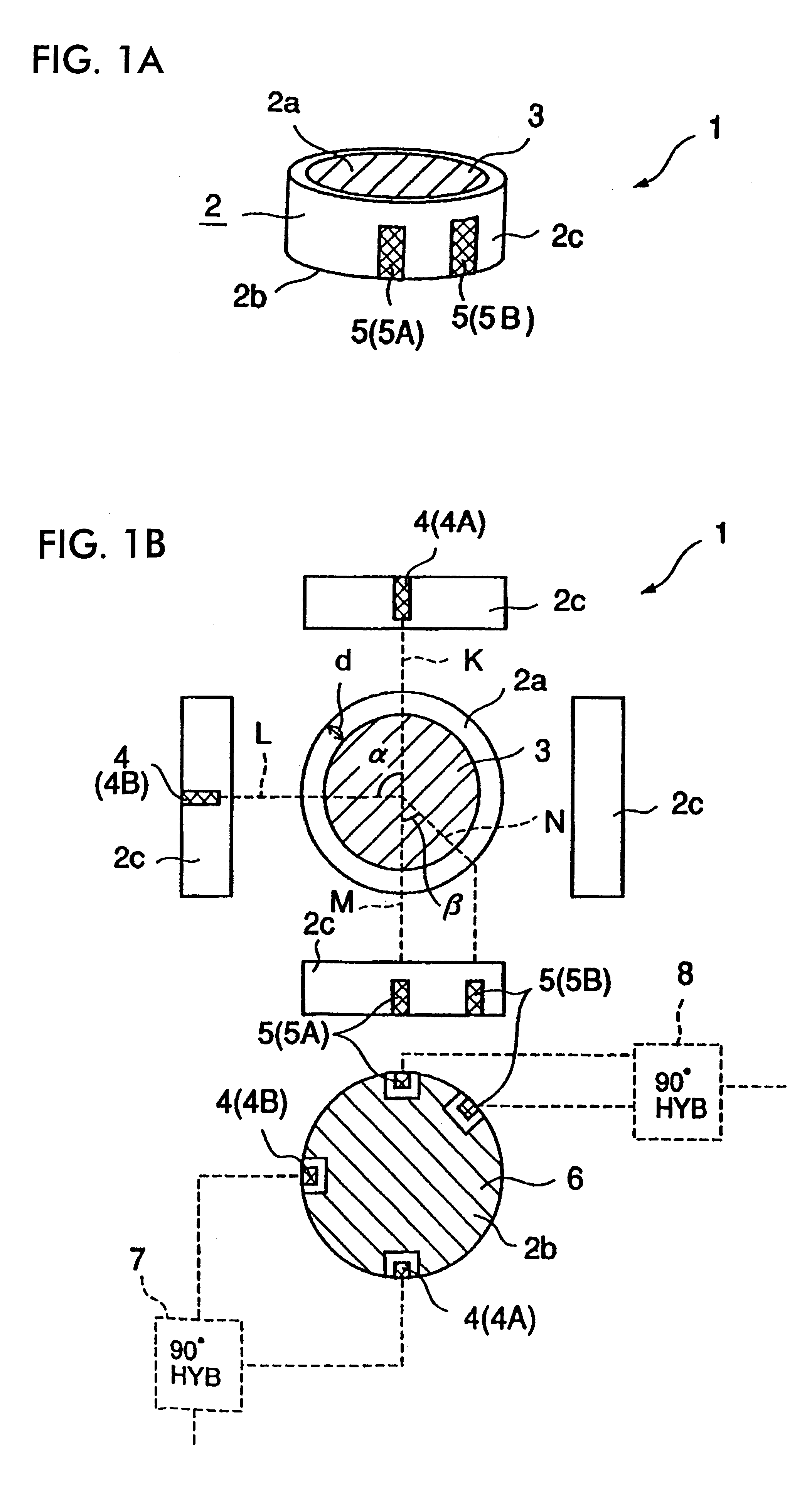
FIG. 1A is a perspective view schematically showing a circularly polarized wave antenna according to the present invention. Moreover,

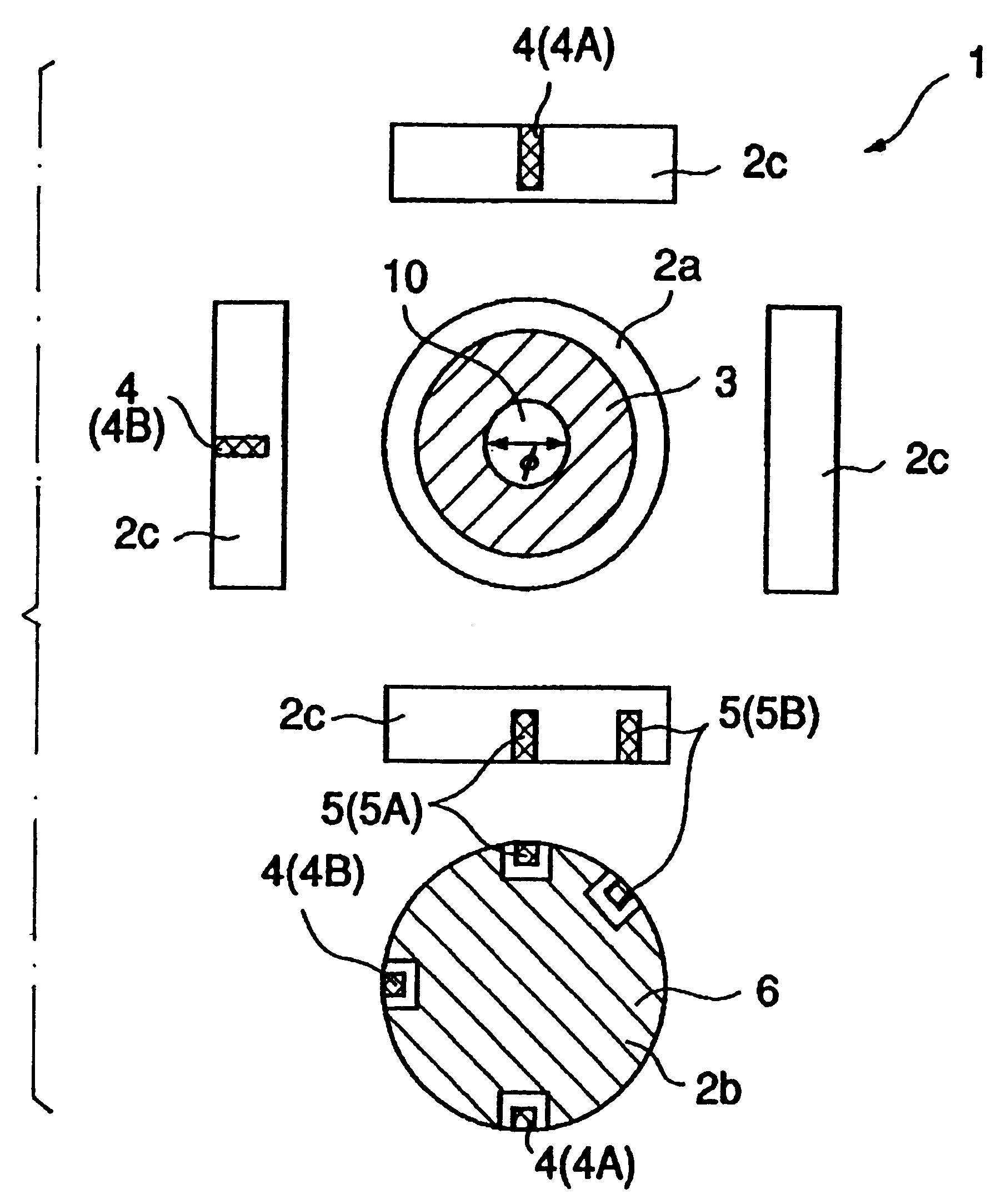
FIG. 1B shows plan views of the circular polarized wave antenna of the above FIG. 1A, taken in the six directions, that is, taken from the upper, under, right, left, front, and back sides thereof, respectively.

As shown in FIGS. 1A and 1B, the circular polarized wave antenna 1 contains a columnar dielectric substrate 2. A circular radiation electrode 3 is formed on the upper face 2a of the dielectric substrate 2. The radiation electrode 3 is formed on the upper face 2a in such a manner that the center of the radiation electrode 3 is positioned on the center axis of the dielectric substrate 2. The distance d between the outer edge of the upper face 2a of the dielectric substrate 2 and the edge of the radiation electrode 3 is substantially constant with respect to the whole peripheral edge of the dielectric substrate 2.

On the side peripheral face 2c of th...
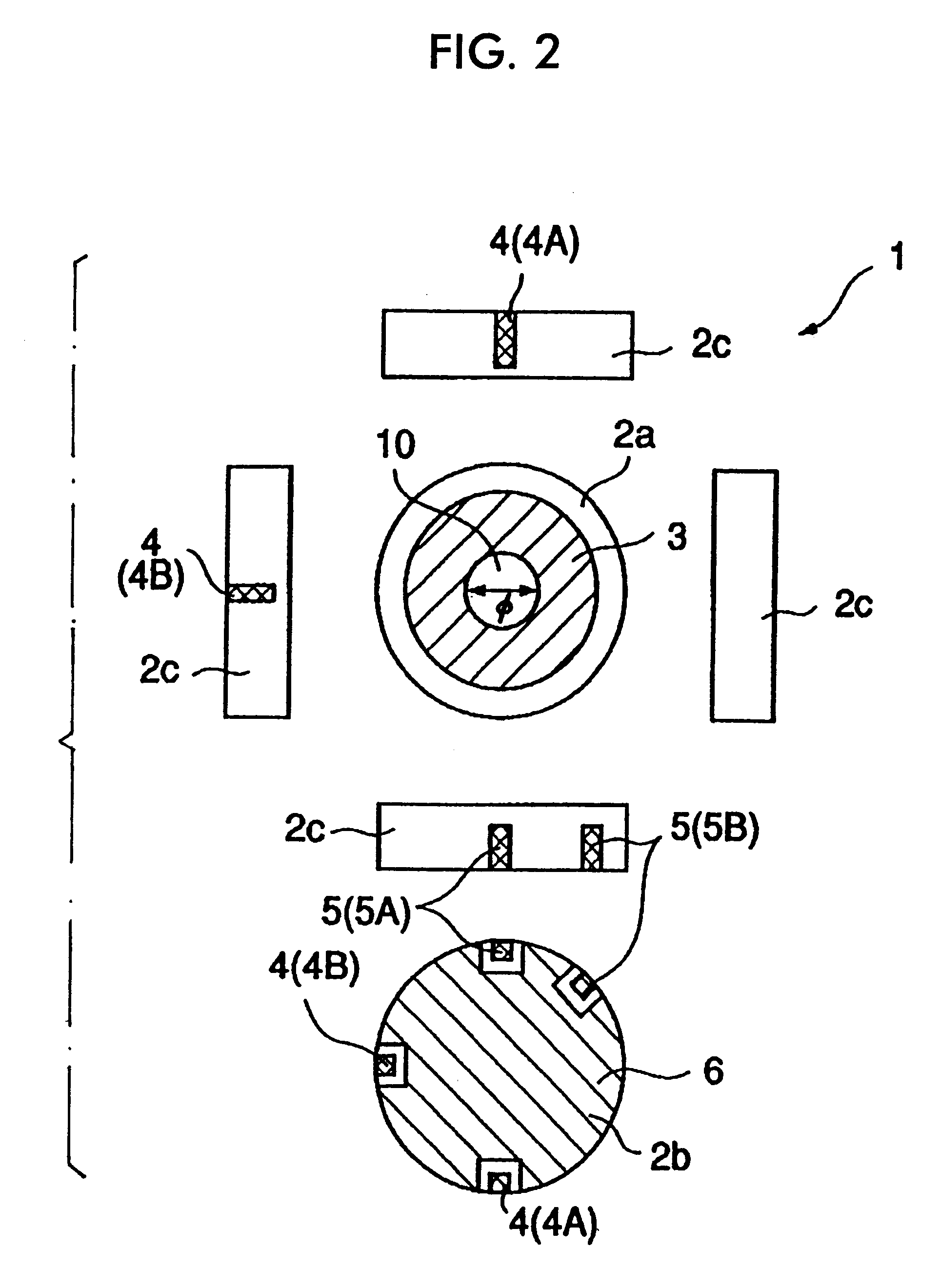
second embodiment

In the second embodiment, the ring-shaped radiation electrode 3 is provided with the center of the ring being positioned on the center axis of the dielectric substrate 2.

The circularly polarized wave antenna 1 of the second embodiment has the same configuration as that of the first embodiment. Thus, needless to say, the antenna 1 of the second embodiment has great advantages comparable to those of the first embodiment. Moreover, in the second embodiment, the radiation electrode 3 is formed in a ring-shape so as to form the non-electrode portion 10. Thus, there are the advantages that adjustment and setting of the interval between the respective resonance frequencies in the fundamental and higher modes can be easily carried out. The reason is as follows. There are differences between the current conduction routes and the current distributions of the fundamental and higher modes in the radiation electrode 3. Owing to these differences, the change amount of the resonance frequency in t...

third embodiment

In the third embodiment, as shown in FIG. 3A or 3B, the cross-section of the dielectric substrate 2, taken along a plane parallel to the upper face 2a has the same circular shape as the non-electrode portion 10, the center of the circular cross-section of the through-hole 12 or the concavity 13 is positioned on the central axis of the dielectric substrate 2, the size of the circular cross-section of the through-hole 12 or the concavity 13 is the same as that of the circular non-electrode portion 10, and the edge of the through-hole 12 or the concavity 13 substantially overlaps with the edge of the non-electrode portion 10.

In the third embodiment, since the radiation electrode 3 is formed in a ring-shape so as to produce the non-electrode portion 10, which is enclosed by the radiation electrode 3 similarly to the second embodiment, the interval between the respective resonance frequencies in the fundamental and higher modes can be easily adjusted and set by adjustment and setting of ...


PUM


Abstract

A radiation electrode is formed on the upper face of the substantially columnar dielectric substrate. Feed electrodes for a fundamental mode and for a higher mode are formed on the side peripheral face of the dielectric substrate. Power is supplied through the respective feed electrodes to the radiation electrode via capacitive coupling. The radiation electrode has both of the functions in the fundamental and higher modes. Thus, the circular polarized wave antenna can be reduced in size. Furthermore, since a capacitive feeding system is employed as described above, the respective resonance frequencies in the fundamental and higher modes can be easily adjusted and set at predetermined frequencies. Also, the circularly polarized wave characteristics in the fundamental and higher modes can be easily enhanced, respectively.

Description

1. Field of the InventionThe present invention relates to a circularly polarized wave antenna for transmitting--receiving a circularly polarized radio wave, and a communication device using the same.2. Description of the Related ArtFIG. 6A is a schematic perspective view of a circularly polarized wave antenna contained in a radio wave device. FIG. 6B is a cross sectional view of a part taken along line a--a in FIG. 6A. The circularly polarized wave antenna 30 shown in FIGS. 6A and 6B is a circularly polarized wave micro-strip antenna described in Japanese Examined Patent Application Publication No. 7-46762. With the circularly polarized wave antenna 30, transmission--reception of radio waves in plural different frequency bands is realized. The circularly polarized wave antenna 30 can correspond to plural different systems such as GPS (Global Positioning System) and S-DAB (DAB(Digital Audio Broadcast) using an S band), and so forth.The circularly polarized wave antenna 30 has the dou...

Claims


Application Information

Patent Timeline
Patent Type & Authority Patents(United States)
IPC IPC(8): H01Q1/24H01Q9/04H01Q13/08H01Q1/38H01Q5/00H01Q5/10H01Q5/35
CPCH01Q9/0435H01Q1/243
Inventor KAWAHATA, KAZUNARIITO, SHIGEKAZUYUASA, ATSUYUKIAKIYAMA, HISAHI
Owner MURATA MFG CO LTD
Why Eureka
Try Eureka