Fuser members having increased thermal conductivity and methods of making fuser members

Inactive Publication Date: 2002-05-28
XEROX CORP
View PDF11 Cites 56 Cited by
  • Summary
  • Abstract
  • Description
  • Claims
  • Application Information

AI Technical Summary

Problems solved by technology

Particularly, release performance degrades as the filler material content in the outer layer of the fuser member increases.
Accordingly, by reducing the content of the filler material that needs to be added in the outer layer to achieve desired t

Method used


Image

  • Fuser members having increased thermal conductivity and methods of making fuser members
  • Fuser members having increased thermal conductivity and methods of making fuser members
  • Fuser members having increased thermal conductivity and methods of making fuser members

Examples


Embodiment Construction

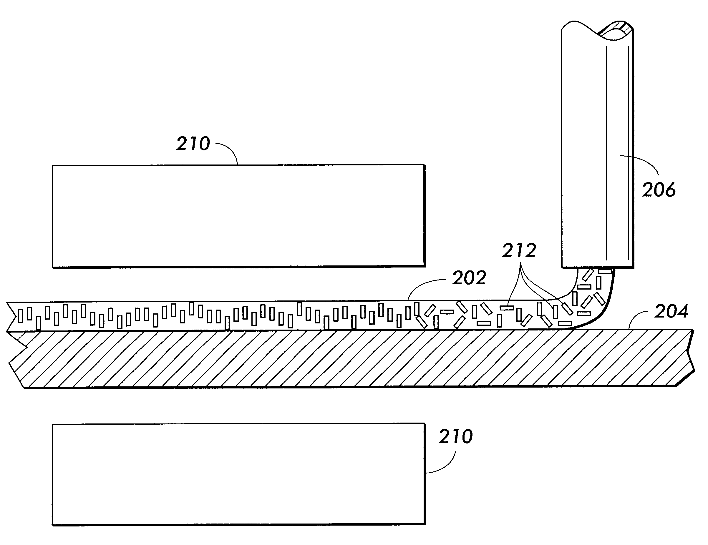
Samples 1-9 are formed by mechanically blending silicone elastomer containing different amounts of iron oxide filler material and pouring the blended material into an aluminum mold. Samples 2, 4, 6 and 8 and the aluminum mold are passed through a magnetic field induced by suspended permanent magnets. Samples 1, 3, 5 and 7 are not passed through the magnetic field. Samples 1-9 are heated to cure the blended elastomer. The samples have an average thickness of about 0.2 mm.

The test results are shown in the following TABLE.

In the TABLE, the term "unoriented" means that the filler material is not oriented by the application of a magnetic field. The term "oriented" means that the filler material is oriented by the application of a magnetic field. For Samples 2, 4, 6 and 8, the percentage of the filler material that is oriented by the magnetic field is about 50%.

The samples are tested to determine their thermal conductivity at a temperature of about 350.degree. F. using a Dynatech-Model C-...


PUM


Abstract

Fuser members having improved thermal conductivity include an outer layer composed of elastomers and filler materials. The filler materials are oriented in the outer layer to provide directional thermal conductivity. Processes for forming the fuser members apply a liquid coating over a substrate and apply a magnetic field to the coating to orient the filler material. The coating is cured to retain the orientation of the filler material in the outer layer.

Description

BACKGROUND OF THE INVENTION 1. FIELD OF INVENTIONThis invention relates to fuser members for fusing toner images in imaging apparatus. This invention also relates to methods of making the fuser members. 2. Description of Related ArtIn electrostatographic imaging apparatus, a light or digital image of an original to be copied is recorded as an electrostatic latent image on a photosensitive member and the latent image is subsequently rendered visible by the application of toner to the photosensitive member. The toner image is then fixed or fused upon a support. The support can be, for example, the photosensitive member itself or a support sheet, such as paper.Thermal energy is generally used to fix toner images onto support members. To permanently fuse toner material onto a support surface by the application of heat, the toner material is heated to cause the toner to flow into the support member. During cooling of the toner material, it solidifies and becomes firmly bonded to the supp...

Claims


Application Information

Patent Timeline
IPC IPC(8): G03G15/20
CPCG03G15/2057
Inventor RIEHLE, GEORGE A.LYND, LAURENCE J.AMICO, MARK S.
Owner XEROX CORP
Why Eureka
Try Eureka