Receiver-integrated condenser

a condenser and receiver technology, applied in refrigeration and liquid refrigerants, refrigeration machines, lighting and heating apparatus, etc., can solve the problems of reducing the super-cooling performance reducing the super-cooling degree of high-pressure side liquid refrigerant in the refrigerant cycle, and reducing the super-cooling degree of liquid refrigerant in the super-cooling portion

Inactive Publication Date: 2002-06-04
DENSO CORP
View PDF12 Cites 37 Cited by
  • Summary
  • Abstract
  • Description
  • Claims
  • Application Information

AI Technical Summary

Benefits of technology

It is an another object of the present invention to provide a receiver-integrated condenser in which a refrigerant passage structure is made simple and an arrangement position of a super-cooling member is readily set.
According to a further another aspect of the present invention, a hole forming method for forming a communication hole in a partition member for partitioning an interior portion of a pipe-like outer wall of a heat exchanger into plural spaces includes: inserting a punch member in a space between the partition member and the outer wall at a predetermined position; attaching and contacting a pressing jig onto the punch member through a hole portion provided in the outer wall; and adding a press force to the punch member by the pressing jig so that the partition member is punched by the punch member to form the communication hole. Thus, pressing force is vertically applied from a directly upper side of the punch member to the punch member by using the pressing jig attached through the hole portion of the outer wall. As a result, punch load is accurately applied to the partition member, and the communication hole is accurately punched. Accordingly, when the hole forming method is applied to a receiver-integrated condenser, a communication hole is readily formed in a partition member.

Problems solved by technology

However, because a super-cooling portion for super-cooling liquid refrigerant separated in the receiver is not provided, a super-cooling degree of high-pressure side liquid refrigerant in a refrigerant cycle is not improved.
Thus, the lower side of the condensing unit is restricted from cooling, and the super-cooling performance of liquid refrigerant in the super-cooling portion is greatly reduced.

Method used


Image

  • Receiver-integrated condenser
  • Receiver-integrated condenser
  • Receiver-integrated condenser

Examples


first embodiment

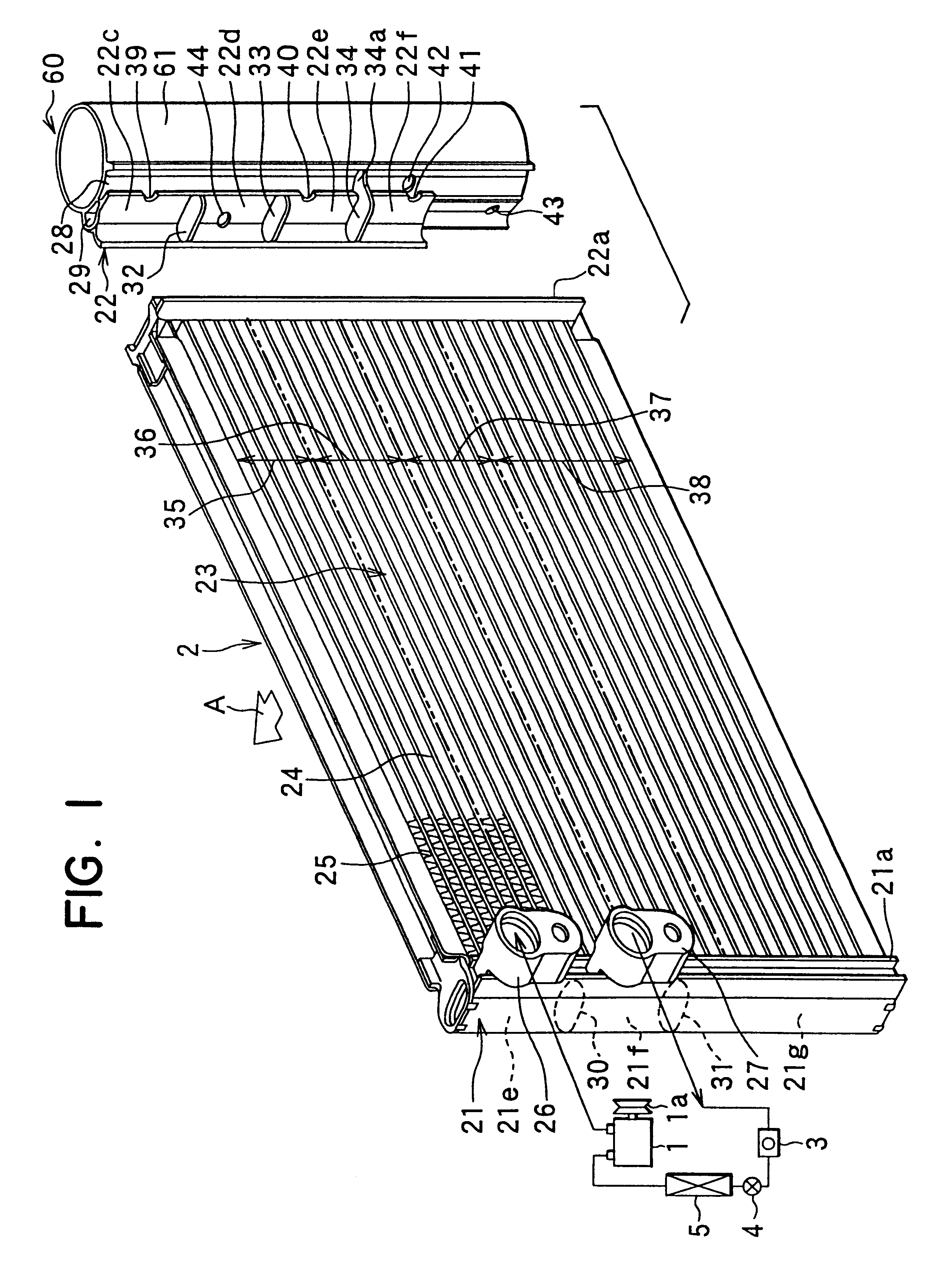
A first preferred embodiment of the present invention will be now described with reference to FIGS. 1-7. In the first embodiment, the present invention is typically applied to a receiver-integrated condenser of a refrigerant cycle of a vehicle air conditioner. As shown in FIG. 1, The refrigerant cycle of the vehicle air conditioner includes a refrigerant compressor 1, a receiver-integrated condenser 2, a sight glass 3, a thermal expansion valve 4, and a refrigerant evaporator 5. All of components of the refrigerant cycle are serially connected by a metal pipe or a rubber pipe to form a closed refrigerant circuit.

The compressor 1 is connected to a vehicle engine disposed within an engine compartment through a belt and an electromagnetic clutch 1a. When the rotation power of the engine is transmitted to the compressor 1 through the electromagnetic clutch 1a, the compressor 1 compresses gas refrigerant sucked therein from the evaporator 5 and then discharges high-pressure high-temperat...

second embodiment

Thus, in the second embodiment, the gas-liquid state of the refrigerant at the outlet of the receiving unit 61 is directly checked from a sight glass 3. That is, as shown in FIGS. 8, 9, the sight glass 3 is disposed in a cover member 45 for closing upper end openings of the second header tank 22 and the receiving unit 61 at an upper position of the second refrigerant passage 29 into which liquid refrigerant from the bottom portion of the receiving unit 61 flows.

As shown in FIGS. 9-11, the cover member 45 includes a first cover portion 45a for closing the upper end opening of the second header tank 22, and a second cover portion 45b for closing the upper end opening of the receiving unit 61. The first cover portion 45a and the second cover portion 45b are formed integrally.

In the cover member 45, as shown in FIG. 10, a circular recess portion 45c for accommodating the sight glass 3 is formed at the upper position of the second refrigerant passage 29 between the first and second cover...

third embodiment

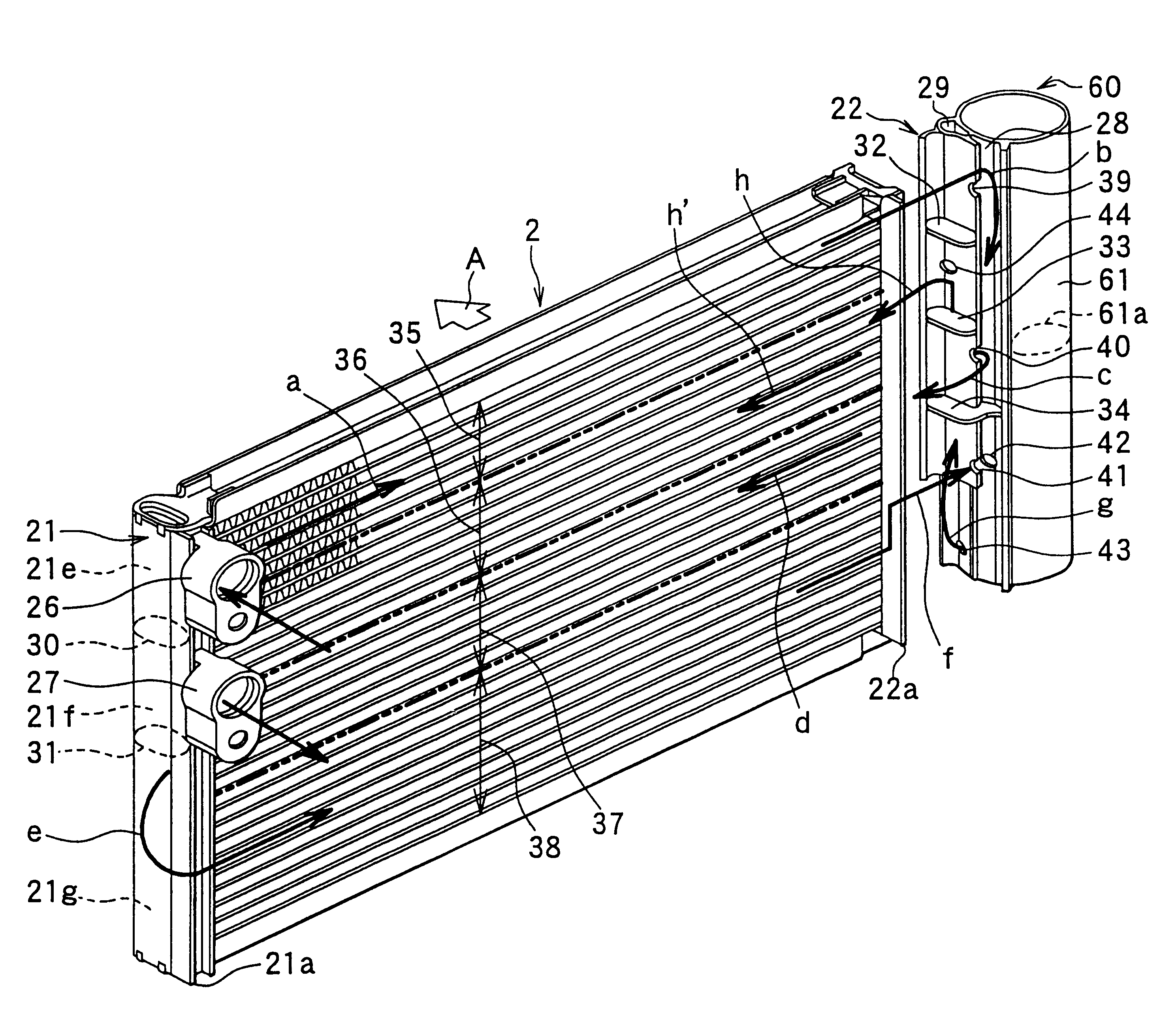
Thus, in the third embodiment, the inlet joint block 26 is disposed to communicate with the lower space 21g among the three spaces 21e, 21f, 21g separated by the first and second separators 30, 31 in the first header tank 21, and the outlet joint block 27 is disposed to communicate with the upper space 21e in the first header tank 21.

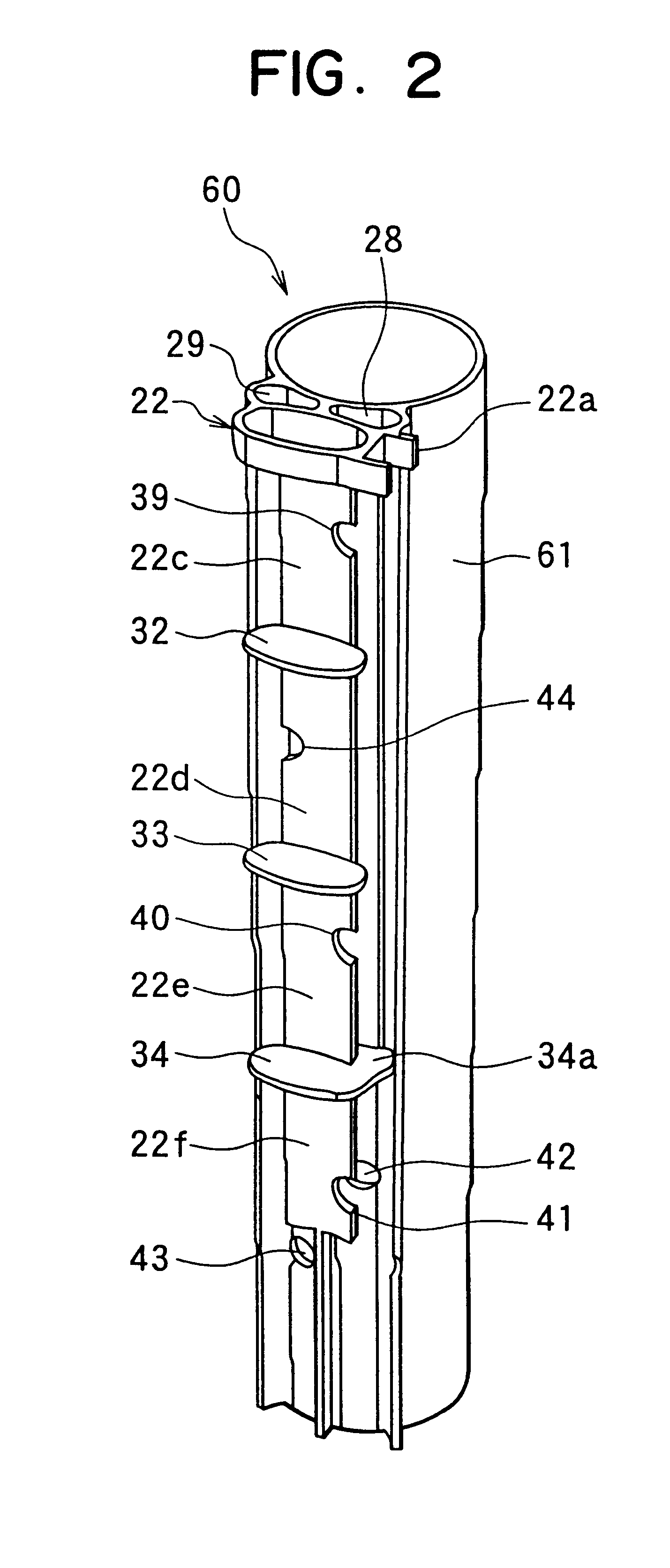
On the other hand, first and second separators 32, 33 are disposed in the second header tank 22. The first separator 32 is disposed in the second header tank 22 at a height position equal to the first separator 30 within the first header tank 21, and the second separator 33 is disposed in the second header tank 22 at a height position between the first and second separators 30, 31 within the first header tank 21. Thus, an interior space of the second header tank 22 is partitioned into upper, middle and lower three spaces 22c, 22d, 22e.

Next, a refrigerant flow in the receiver-integrated condenser 2 according to the third embodiment will be now described ...


PUM


Abstract

In a receiver-integrated condenser, a super-cooling portion for cooling liquid refrigerant from a receiving unit is disposed between first and second condensing portions in a core portion in a vertical direction. Therefore, in an engine-idling, even when high-temperature air having passed through the receiver-integrated condenser is introduced again toward an upstream air side of the receiver-integrated condenser through a lower side of the receiver-integrated condenser, the high-temperature air is not introduced toward the arrangement position of said super-cooling portion, because the super-cooling portion is positioned at an upper side from the second condensing portion. Thus, super-cooling performance of refrigerant in the super-cooling portion of the core portion is prevented from being decreased even in the engine idling.

Description

This application is related to and claims priority from Japanese Patent Applications No. Hei. 11-59254 filed on Mar. 5, 1999, No. Hei. 11-194793 filed on Jul. 8, 1999 and No. Hei. 11-324570 filed on Nov. 15, 1999, the contents of which are hereby incorporated by reference.1. Field of the InventionThe present invention relates to a receiver-integrated condenser in which a condensing portion for cooling and condensing refrigerant, a receiving unit for separating gas refrigerant and liquid refrigerant from the condensing portion, and a super-cooling portion for super-cooling liquid refrigerant from the receiving unit are integrally formed. The receiver-integrated condenser is suitably used for a vehicle air conditioner.2. Description of Related ArtJP-A-5-141812 describes a receiver-integrated condenser in which a condensing unit for condensing refrigerant and a receiving unit for separating refrigerant from the condensing unit into gas refrigerant and liquid refrigerant are integrally ...

Claims


Application Information

Patent Timeline
Patent Type & Authority Patents(United States)
IPC IPC(8): F28F9/02F25B39/04F25B43/00F28F9/04
CPCF25B39/04F28F9/0212F28F9/0246F25B2339/044F28F2220/00F25B2400/162
Inventor AKI, YOSHIFUMIHASEGAWA, ETUOMATSUO, HIROKINOBUTA, TETSUJIYAMAMOTO, MICHIYASUKAZUHIRO, MITSUKAWAOKABAYASHI, EIJI
Owner DENSO CORP
Why Eureka
Try Eureka