Control device of automotive pivoting door

a technology of control device and pivoting door, which is applied in the direction of doors, roofs, wing accessories, etc., can solve the problems of door not being stopped at the desired half-open position, back door cannot be fully opened,

Inactive Publication Date: 2002-06-04
MITSUI KINZOKU ACT
View PDF9 Cites 69 Cited by
  • Summary
  • Abstract
  • Description
  • Claims
  • Application Information

AI Technical Summary

Problems solved by technology

However, due to inherent construction, during its pivoting, the rear end of the door becomes largely projected rearward.
Thus, if the vehicle is parked in a limited area where only a small space is left behind the vehicle, the back door can not be fully opened.
However, even this door fails to be stopped at a desired half-open position.

Method used


Image

  • Control device of automotive pivoting door
  • Control device of automotive pivoting door
  • Control device of automotive pivoting door

Examples


first embodiment

FIG. 4 shows a block diagram of an electric circuit employed in the present invention.

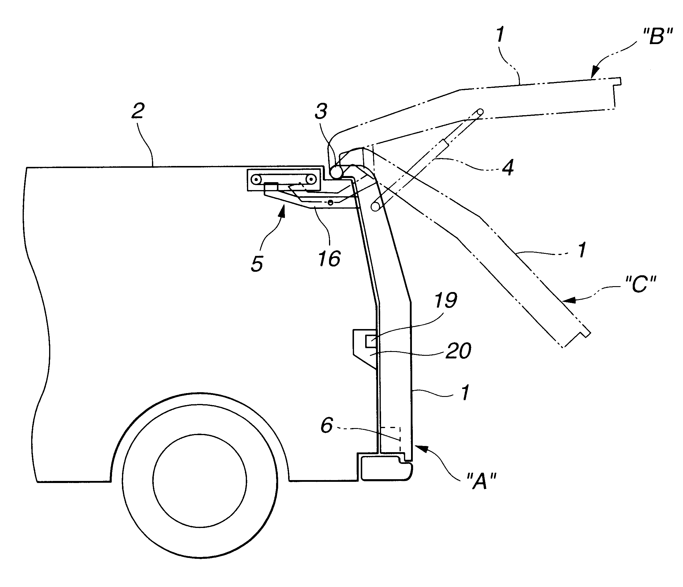
In the drawing, denoted by numeral 19 is a door operation switch unit which is mounted on a rear combination lamp 20 (see FIG. 7) of the vehicle. The door operation switch unit 19 comprises a door open switch 19a and a door close switch 19b. As will become apparent as the description proceeds, the door operation switch unit 19 also serves as a door stop switch.

Information signals from the switches 19a and 19b are led to an operation judgment and actuation determination circuit 21 of a control unit CU. It is to be noted that this control unit CU is constructed of a microcomputer that comprises a central processing unit (CPU), a random access memory (RAM), a read only memory (ROM) and input and output interfaces.

Thus, by analyzing the information signals, the circuit 21 judges the operation of the switches 19a and 19b, and based on the judgment, the circuit 21 decides an actuation manner that the mot...

second embodiment

Referring to FIG. 8, there is shown a block diagram of an electric circuit employed in the present invention.

Since the second embodiment is similar to the above-mentioned first embodiment, only portions that are different from those of the first embodiment will be described in the following.

In the second embodiment, a different electric clutch 9' is used in place of the above-mentioned clutch 9. That is, in addition to the above-mentioned engaged and disengaged conditions, the clutch 9' employed in the second embodiment has further a so-called half-engaged condition. By assuming this half-engaged condition, the clutch 9' can provide a manual pivoting movement of the door 1 with a suitable resistance.

When de-energized, the clutch 9' assumes the disengaged condition thereby to cut off the power transmission path from the motor 7 to the opening / closing mechanism 10. Under this condition, the power transmission from the motor 7 to the mechanism 10 is suppressed. When energized by a larg...


PUM


Abstract

A motor vehicle has a pivoting door that pivots upward and downward. A control device for controlling the pivoting door comprises an electric drive unit that drives the pivoting door by an electric power; a door operation switch that permits the pivoting door to pivot between a full-close position and a full-open position with the aid of the electric drive unit when operated; a movement stopping structure that stops and holds the pivoting door at a half-open position when operated; and a control unit that controls the electric drive unit and the movement stopping structure in accordance with an ON / OFF operation of the door operation switch.

Description

1. Field of the InventionThe present invention relates in general to control devices of automotive doors, and more particularly to control devices for controlling movement of an automotive pivoting door, such as a vertically pivoting back door or the like.2. Description of the Prior ArtUsually, wagon type motor vehicles and the like are equipped with openable back doors for facilitating loading and unloading work. Some of such doors are of a vertically pivoting type that pivots upward and downward about a rear end of a vehicle roof. However, due to inherent construction, during its pivoting, the rear end of the door becomes largely projected rearward. Thus, if the vehicle is parked in a limited area where only a small space is left behind the vehicle, the back door can not be fully opened. In this case, the work for loading and unloading has to be made with the door halfly opened. That is, the worker has to carry out the loading / unloading work awkwardly holding the door at such half...

Claims


Application Information

Patent Timeline
Patent Type & Authority Patents(United States)
IPC IPC(8): B60J5/10E05F15/12
CPCE05F15/63E05F15/627E05Y2201/21E05Y2201/236E05Y2201/246E05Y2201/25E05Y2201/26E05Y2201/462E05Y2800/11E05Y2900/546E05Y2201/266
Inventor YUGE, MASAAKI
Owner MITSUI KINZOKU ACT
Why Eureka
Try Eureka