Transmission cover and supporting arrangement for all terrain vehicle

a technology for all terrain vehicles and transmission covers, applied in the direction of frictional roller based transmission, gearing, cycle equipment, etc., can solve the problem of high bending force of the drive sha

Inactive Publication Date: 2002-06-04
YAMAHA MOTOR CO LTD
View PDF12 Cites 46 Cited by
  • Summary
  • Abstract
  • Description
  • Claims
  • Application Information

AI Technical Summary

Problems solved by technology

Moreover, the driveshaft experiences a high level o...

Method used


Image

  • Transmission cover and supporting arrangement for all terrain vehicle
  • Transmission cover and supporting arrangement for all terrain vehicle
  • Transmission cover and supporting arrangement for all terrain vehicle

Examples


Embodiment Construction

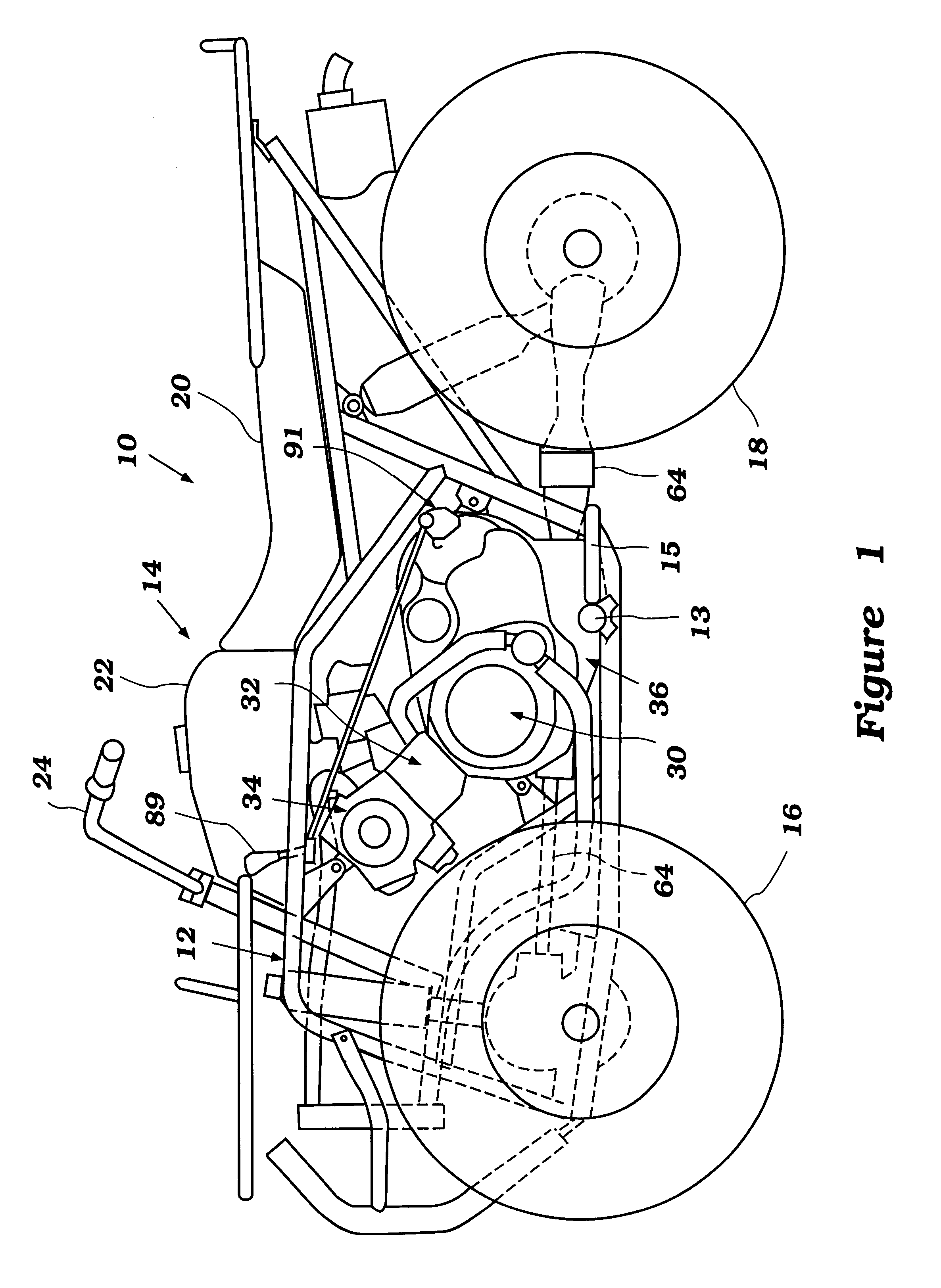
With reference initially to FIG. 1, an all terrain vehicle configured and arranged in accordance with certain features, aspects and advantages of the present invention will be described in detail. The illustrated vehicle, indicated generally by the reference numeral 10, provides an exemplary environment in which the present crankcase cover shaft supporting arrangement will be described. While the illustrated vehicle 10 is a small stature four-wheel all terrain vehicle, one of ordinary skill in the art will readily recognize that the present invention may find utility in a variety of other vehicles as well.

With continued reference to FIG. 1, the vehicle 10 is generally comprised of a frame 12, a body 14, a pair of front wheels 16 and a pair of rear wheels 18 assembled in any suitable manner. The frame 12 is typically of a welded construction and generally defines, in part, a centrally located engine compartment. A foot peg 13 and foot board structure 15 may be attached to the frame i...


PUM


Abstract

An all terrain vehicle has a crankcase cover and shaft supporting arrangement through which a shaft of a transmission is mounted between the crankcase and a crankcase cover. The arrangement includes a spider bracket having a bearing carrier and a cover member attached to the crankcase through the spider arrangement. The crankcase cover is preferably made of a less thermally conductive material as compared to the spider.

Description

1. Field of the InventionThe present invention generally relates to a transmission arrangement for all terrain vehicles. More particularly, the present invention relates to a cover and shaft supporting arrangement for such a transmission.2. Description of the Related ArtAll terrain vehicles have begun employing variable speed transmissions. Such variable speed transmissions utilize a drive pulley that may be coupled to a crankshaft of an engine through any suitable mechanism. The drive pulley, in turn, may be connected to a driven pulley through a belting arrangement such that as the belt rotates under the force of the drive pulley, the driven pulley is also rotated.In some vehicles, the driven pulley may be carried upon an output shaft that extends into a crankcase of the all terrain vehicle. This output shaft is often carried by two sets of bearings carried within the crankcase and arranged along the output shaft such that the output shaft is cantilevered outwards to receive the d...

Claims


Application Information

Patent Timeline
IPC IPC(8): B62M13/00B62J13/00F02B61/02F02B61/00F16H61/66F16H61/662F16H63/02F16H63/06F16H9/12B60K17/04
CPCB62J13/00B62M13/00F16H61/662F02B61/02F16H63/067
Inventor FUKUDA, KAZUTAKA
Owner YAMAHA MOTOR CO LTD
Why Eureka
Try Eureka