
Method and system for operating two or more integrators with different power supplies for an analog-to-digital delta-sigma modulator

a technology of deltasigma modulator and integrator, which is applied in the field of analog-to-digital converter, can solve the problems of significant increase in the cost of the chip, add at least some noise, and significantly increase the size and capacitor area of the capacitor

Inactive Publication Date: 2002-06-04
CIRRUS LOGIC INC
View PDF1 Cites 37 Cited by
  • Summary
  • Abstract
  • Description
  • Claims
  • Application Information

AI Technical Summary

Problems solved by technology

However, due to inherent noise of electrical circuits, the electrical circuits of ADCs add at least some amount of noise (e.g., predominantly including but not limited to thermal noise) to the signals.
The approach of reducing noise power in this manner results in the disadvantages of having to significantly increase the capacitor size and capacitor area.
The cost of the chip would significantly increase if the capacitor size and area would have to be increased.
Furthermore, the analog circuits that are "upstream" in the ADC do not more easily limit the dynamic range of the system.
However, the increase of the signal power results in some problems.
Secondly, the high voltage circuits consume a more significant amount of power than respective low voltage circuits.
However, physically large components, such as large-sized transistors, are needed for the A / D converter to operate under the large voltage.
The use of physically large components makes the size and cost of the A / D converter chip respectively larger and higher.
Also, since a large power voltage drives the modulator components, then the A / D converter consumes greater overall power.

Method used


Image

  • Method and system for operating two or more integrators with different power supplies for an analog-to-digital delta-sigma modulator
  • Method and system for operating two or more integrators with different power supplies for an analog-to-digital delta-sigma modulator
  • Method and system for operating two or more integrators with different power supplies for an analog-to-digital delta-sigma modulator

Examples


Embodiment Construction

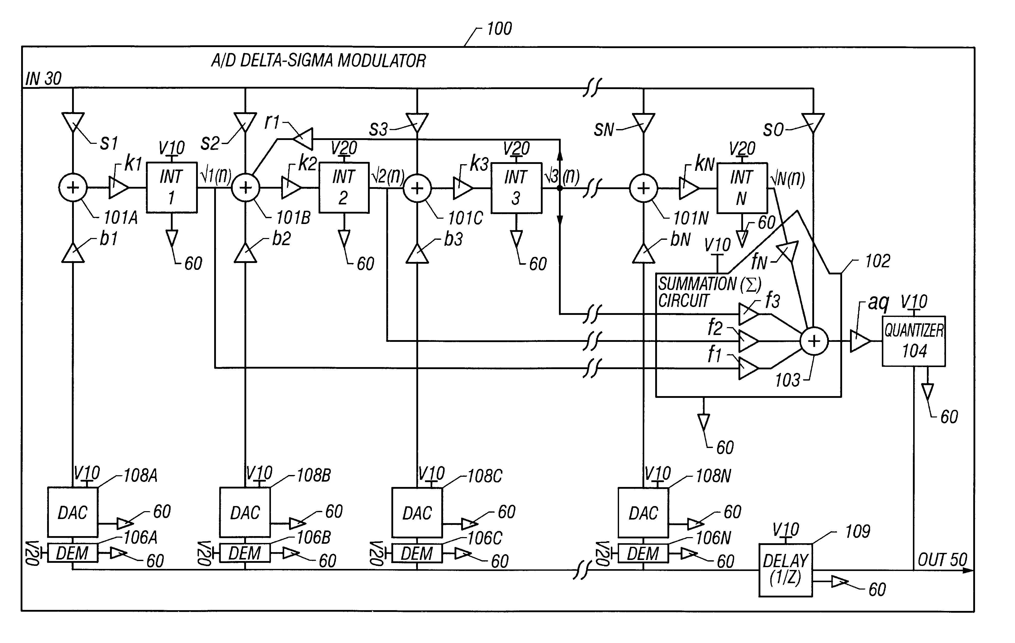
A method and system are disclosed for operating two or more integrator amplifiers with different power supplies for a modulator of an analog-to-digital ("A / D") converter. A first integrator that is an upstream integrator is operated with one power supply, and the other downstream integrator(s) is / are operated with at least another power supply. The coefficients of the modulator are designed so that the gain(s) before the downstream integrator(s) sufficiently attenuate(s) the voltage of the signal so that the power of the signal is within the operating range of the downstream integrator(s).

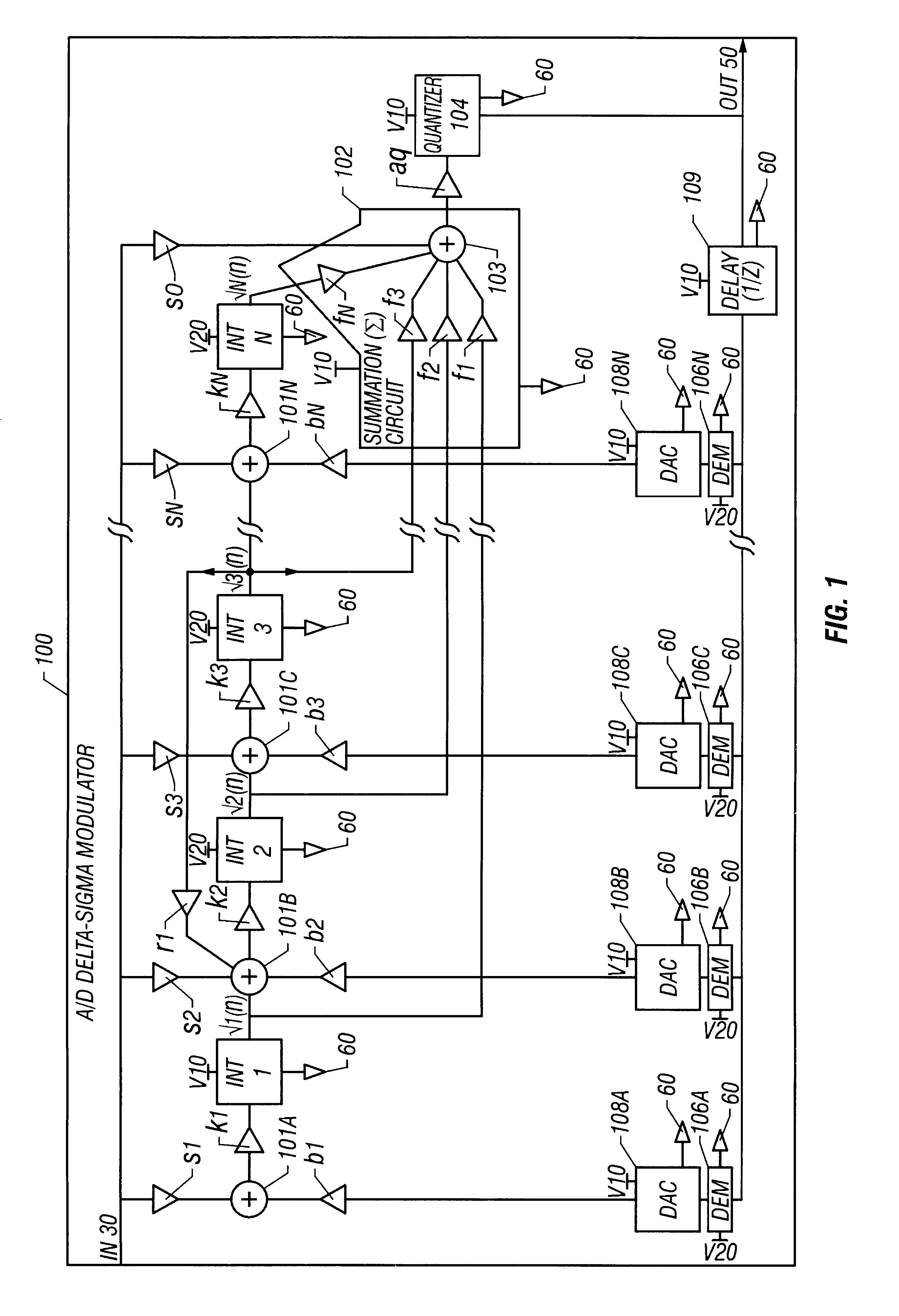
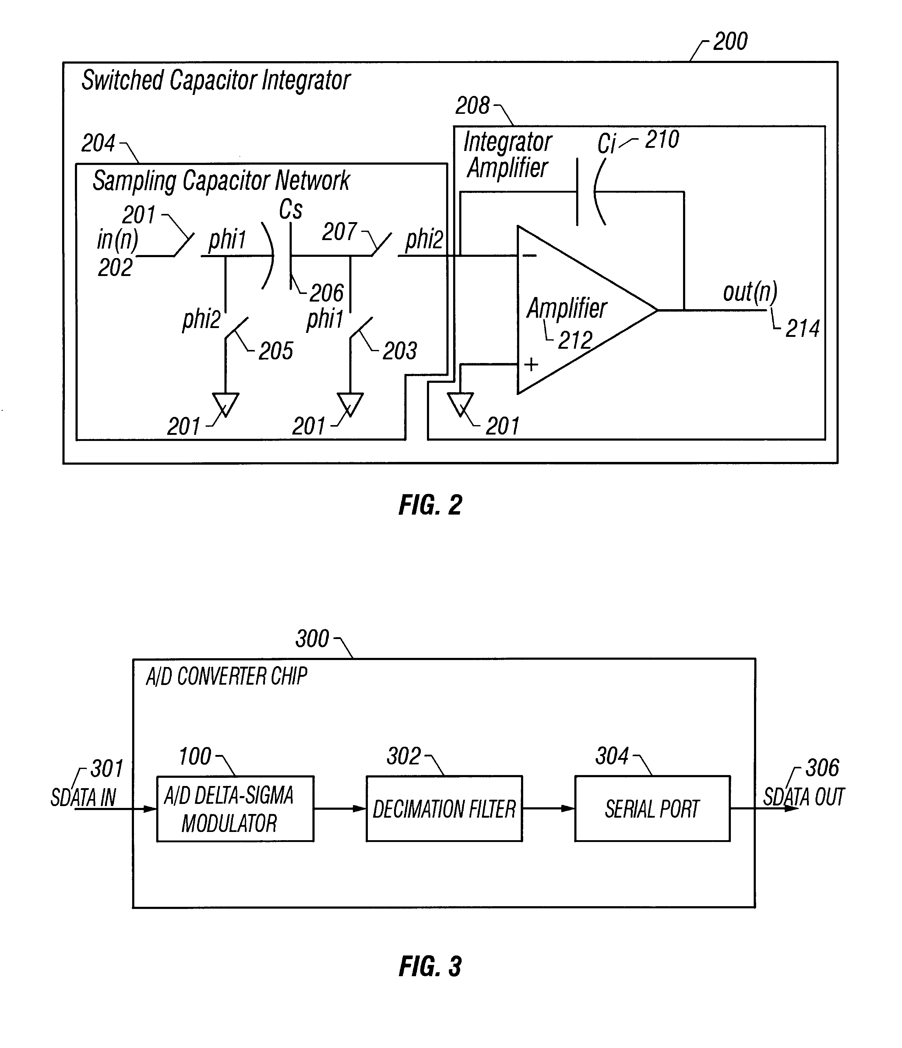
With reference now to FIG. 1, a block diagram of an exemplary delta-sigma modulator 100 for an analog-to-digital ("A / D") converter, such as an A / D converter chip 300 in FIG. 3, in accordance with the present invention is shown. Delta-sigma modulator 100 has integrators 1, 2, 3, . . . N ("INT 1, 2, 3 . . . N") coupled in series as shown in FIG. 1. Integrators 1, 2, 3 . . . N is each coupled to a sum...


PUM


Abstract

A method and system are disclosed for operating two or more integrator amplifiers with different power supplies for a modulator of an analog-to-digital ("A / D") converter. A first, upstream integrator is operated with one power supply, and the other downstream integrator(s) is / are operated with at least another power supply. The modulator has amplifiers with coefficient gains having values that are determined and set so that voltage levels for the at least another integrator are maintained within operating and output limits. An integrating coefficient gain k1 for the first integrator is set to have a sufficiently large value so that an integrating capacitor can be made small for the one integrator. Another integrating coefficient gain k2 for a second integrator is set to have a sufficiently small value so that an output voltage from the first integrator is sufficiently attenuated to a voltage value within an operating range of the second integrator.

Description

CROSS-REFERENCED PATENT APPLICATIONSThis application relates to and cross-references U.S. patent application Ser. No. 09 / 843,196 entitled "METHOD AND SYSTEM FOR OPERATING TWO OR MORE DYNAMIC ELEMENT MATCHING (DEM) COMPONENTS WITH DIFFERENT POWER SUPPLIES FOR A DELTA-SIGMA MODULATOR OF AN ANALOG-TO-DIGITAL CONVERTER" which has been contemporaneously filed on the same date as the present application. The present patent application also cross-references pending U.S. patent application Ser. No. 09 / 591,124 filed on Jun. 9, 2000 to Allen et al. entitled "VOLTAGE LEVEL SHIFTER" (hereafter referred to as "Allen et al. patent application"), which has been assigned to CIRRUS LOGIC, INC., Austin, Tex. The Allen et al. patent application is incorporated by reference herein in its entirety.1. Technical FieldThe present invention relates in general to an analog-to-digital converter, and, in particular, to a modulator for an analog-to-digital ("A / D") converter. Still more particularly, the present...

Claims


Application Information

Patent Timeline
Patent Type & Authority Patents(United States)
IPC IPC(8): H03M3/04H03M3/00H03M3/02
CPCH03M3/32H03M3/424H03M3/454H03M3/452H03M3/448
Inventor TUCKER, JOHN CHRISTOPHER
Owner CIRRUS LOGIC INC
Learn More