Split-queue architecture with a first queue area and a second queue area and queue overflow area having a trickle mode and an overflow mode based on prescribed threshold values

a technology of split-queue and queue, applied in the field of communication systems, can solve the problems of reducing affecting the queue latency, and affecting the overall efficiency of the system,

Inactive Publication Date: 2002-06-04
GLOBALFOUNDRIES INC
View PDF10 Cites 104 Cited by
  • Summary
  • Abstract
  • Description
  • Claims
  • Application Information

AI Technical Summary

Problems solved by technology

Without the use of buffers, there is a great likelihood that data frames will be lost, hence requiring retransmission and reducing the overall efficiency of the system.
The greater the capacity of the queue to store entries, the higher the latency of the queue.
It is often difficult to balance the competing factors of latency and capacity in multiport network switches because of the desire to quickly process received data frames with minimal delay that may be introduced by the queue structure.
Further complications arise as a result of the ever-increasing pressure to reduce the size of the chips that embody the device that implements the queue structure, or provide extended functionality in the device.
Consequently, the amount of real estate, on the chip, that can be dedicated to the queuing function becomes considerably more expensive.
This expense is further increased in devices such as multiport network switches, where each port may be required to have its own queue.
The external storage area, however, introduces new problems because access to the "on-chip" memory is considerably faster than access to the external memory.
Consequently, latency is significantly increased.
Accordingly, a principal problem associated with implementing queue structures is the need to efficiently balance competing factors such as latency and storage capacity.
Another problem associated with implementing queue structures is the inability to effectively minimize latency when a large storage capacity is available.

Method used


Image

  • Split-queue architecture with a first queue area and a second queue area and queue overflow area having a trickle mode and an overflow mode based on prescribed threshold values
  • Split-queue architecture with a first queue area and a second queue area and queue overflow area having a trickle mode and an overflow mode based on prescribed threshold values
  • Split-queue architecture with a first queue area and a second queue area and queue overflow area having a trickle mode and an overflow mode based on prescribed threshold values

Examples


Embodiment Construction

The present invention will be described with the example of a switch in a packet switched network, such as an Ethernet (IEEE 802.3) network. It will become apparent, however, that the present invention is also applicable to other packet switched systems, as described in detail below, as well as to other types of systems in general.

Switch Architecture Overview

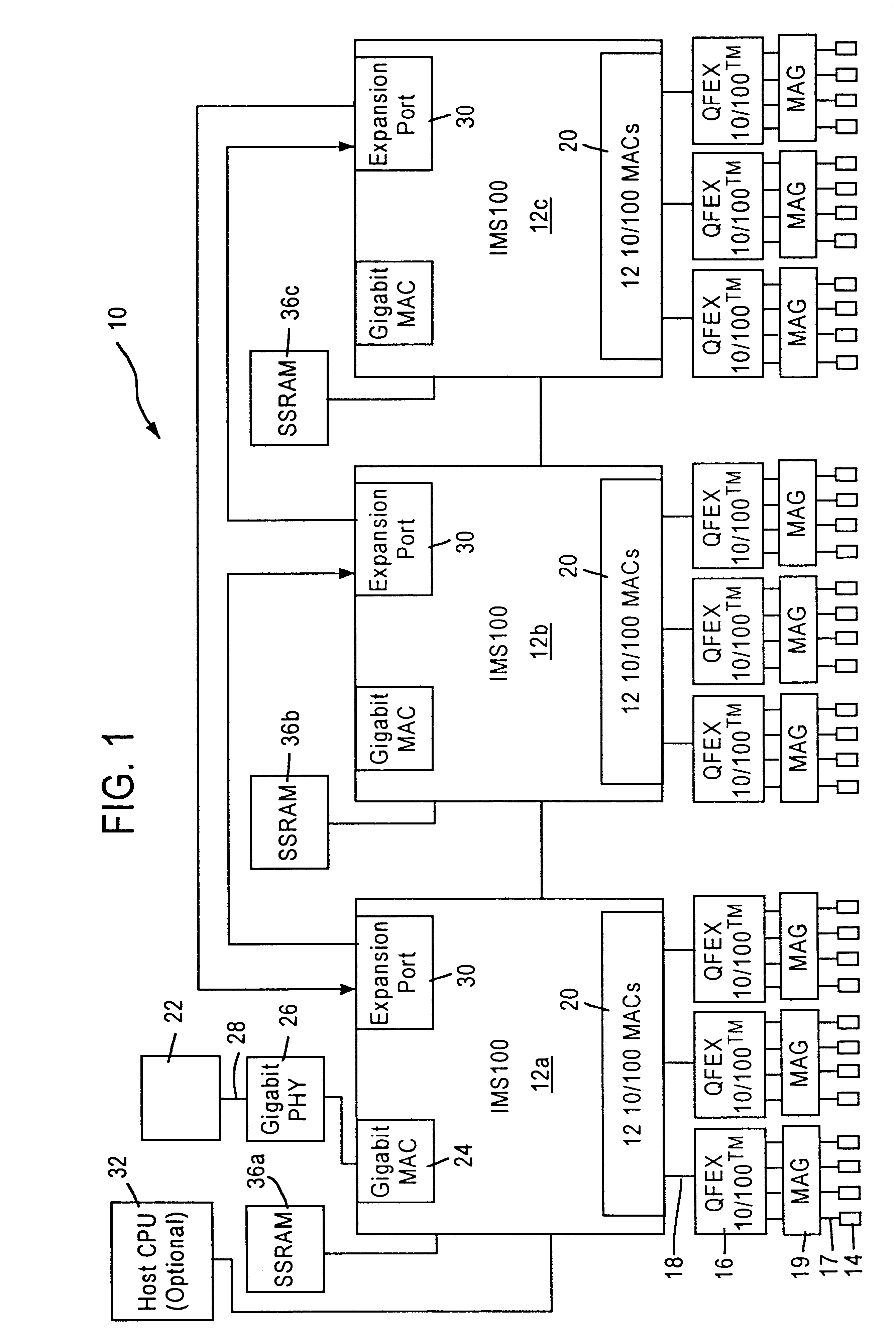
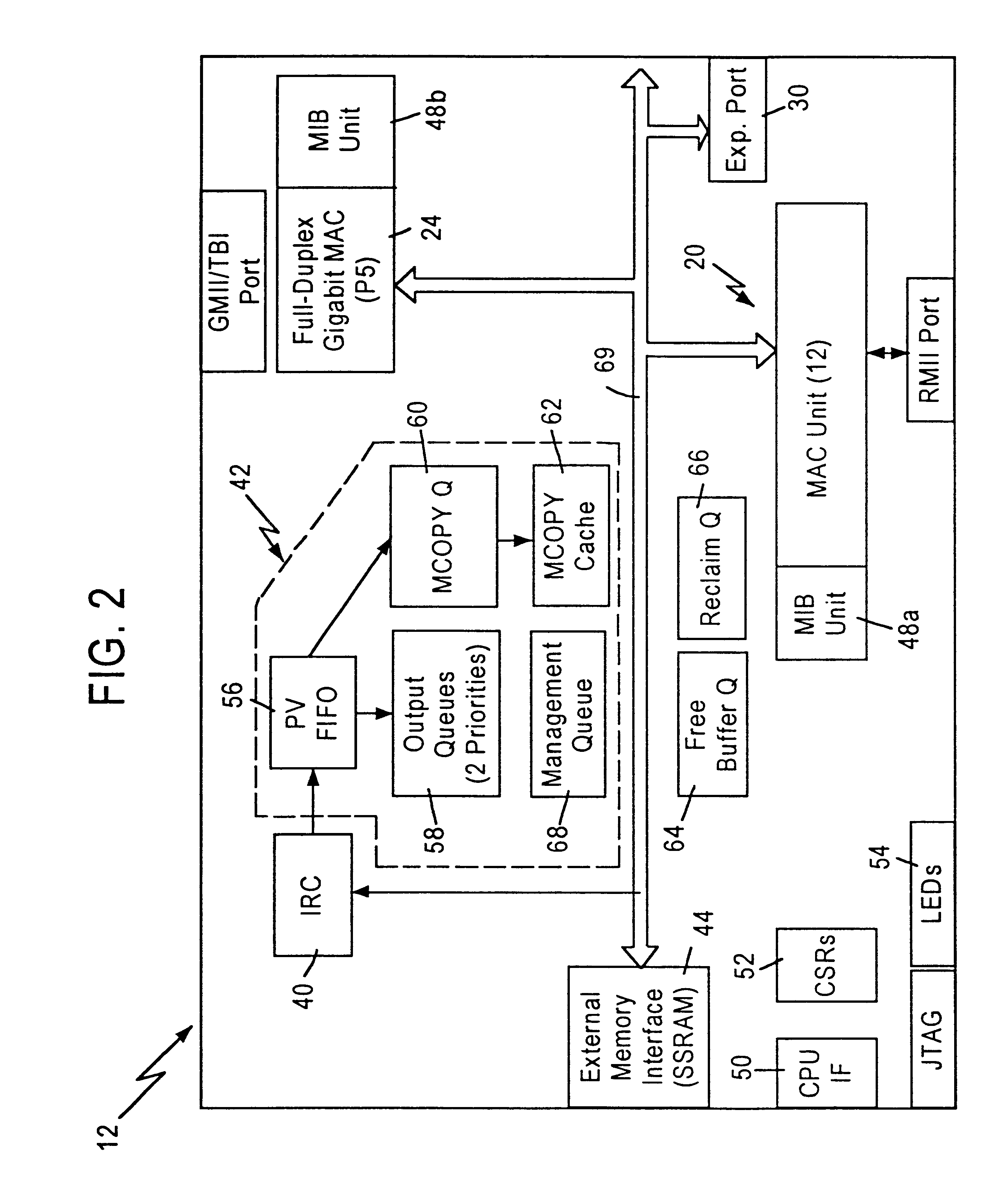
FIG. 1 is a block diagram of an exemplary system in which the present invention may be advantageously employed. The exemplary system 10 is a packet switched network, such as an Ethernet (IEEE 802.3) network. The packet switched network includes integrated multiport switches (IMS) 12 that enable communication of data packets between network stations. The network may include network stations having different configurations, for example twelve (12) 10 megabit per second (Mb / s) or 100 Mb / s network stations 14 (hereinafter 10 / 100 Mb / s) that send and receive data at a network data rate of 10 Mb / s or 100 Mb / s, and a 1000 Mb / s (i.e., 1 ...


PUM


Abstract

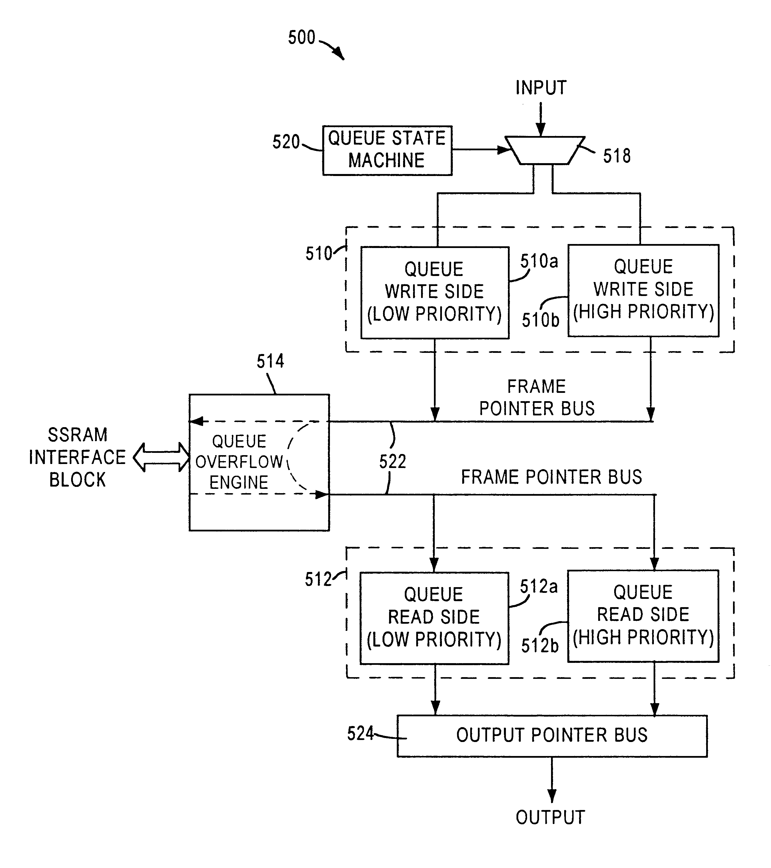
A programmable split-queue structure includes a first queue area for receiving entries, a second queue area for outputting entries input to said first queue area, and a queue overflow engine logically coupled to the first queue area and the second queue area. The queue overflow engine functions to transfer entries from the first queue area to the second queue area using one of two transfer modes. The queue overflow engine selects the most appropriate transfer mode based on a prescribed threshold value that can be dynamically programmed. An overflow storage area having high capacity may be provided in an external memory in order to increase the overall capacity of the queue structure.

Description

1. Field of the InventionThe present invention relates to communication systems, and more particularly, to a method and apparatus for performing diagnostic procedures on queue structures used for storing received data in communication systems.2. Description of the Related ArtModern communication systems, such as computer networking systems or communication networks, provide constant transmission of data between end stations and / or intermediate stations such as routers and signal amplifiers. Computer networking, systems, such as packet switched networks (e.g., Ethernet networks), often require transmission of data to a single end station or to multiple end stations within the network. The data originates from a user program and is segmented into multiple data frames, and subsequently transmitted in order to simplify processing and minimize the retransmission time required for error recovery. For example, in a conventional e-mail system, a user may desire to send the same e-mail messa...

Claims


Application Information

Patent Timeline
Patent Type & Authority Patents(United States)
IPC IPC(8): H04L12/56
CPCH04L47/24H04L47/29H04L47/6215H04L49/9078H04L49/90H04L49/30H04L49/3027H04L49/351
Inventor SANG, JINQLIHYANG, EDWARDERIMLI, BAHADIR
Owner GLOBALFOUNDRIES INC
Why Eureka
Try Eureka