
Horizontal axis type wind turbine and method of construction thereof

a horizontal axis, wind turbine technology, applied in the field of wind turbines, can solve the problems of increasing the procurement cost of construction equipment, and difficulty in securing a work space suitable for construction

Inactive Publication Date: 2002-06-25
SUBARU CORP
View PDF5 Cites 132 Cited by
  • Summary
  • Abstract
  • Description
  • Claims
  • Application Information

AI Technical Summary

Benefits of technology

It is an object of the present invention to provide a method of constructing a relatively large size, horizontal axis type wind turbine capable of reducing construction cost without using a crane of large size.

Problems solved by technology

However, using the large size mobile crane and the like incurs an increase of procurement cost of construction equipment.
Particularly, in case of construction works in islands, mountains, remote places and the like, the construction equipment procurement cost would increase.
Furthermore, there would be a difficulty in securing a work space suitable for construction.
Further, the maintenance cost would increase because of the necessity for a large size crane.
As a result, there are many cases where the construction of wind turbines must avoidably given up in spite of the fact that the power supply by wind turbines is most desired in these islands, mountains, remote places and the like and the case is similar with underdevelopment countries where the procurement of construction equipments like large size of cranes is generally difficult.

Method used


Image

  • Horizontal axis type wind turbine and method of construction thereof
  • Horizontal axis type wind turbine and method of construction thereof
  • Horizontal axis type wind turbine and method of construction thereof

Examples


Embodiment Construction

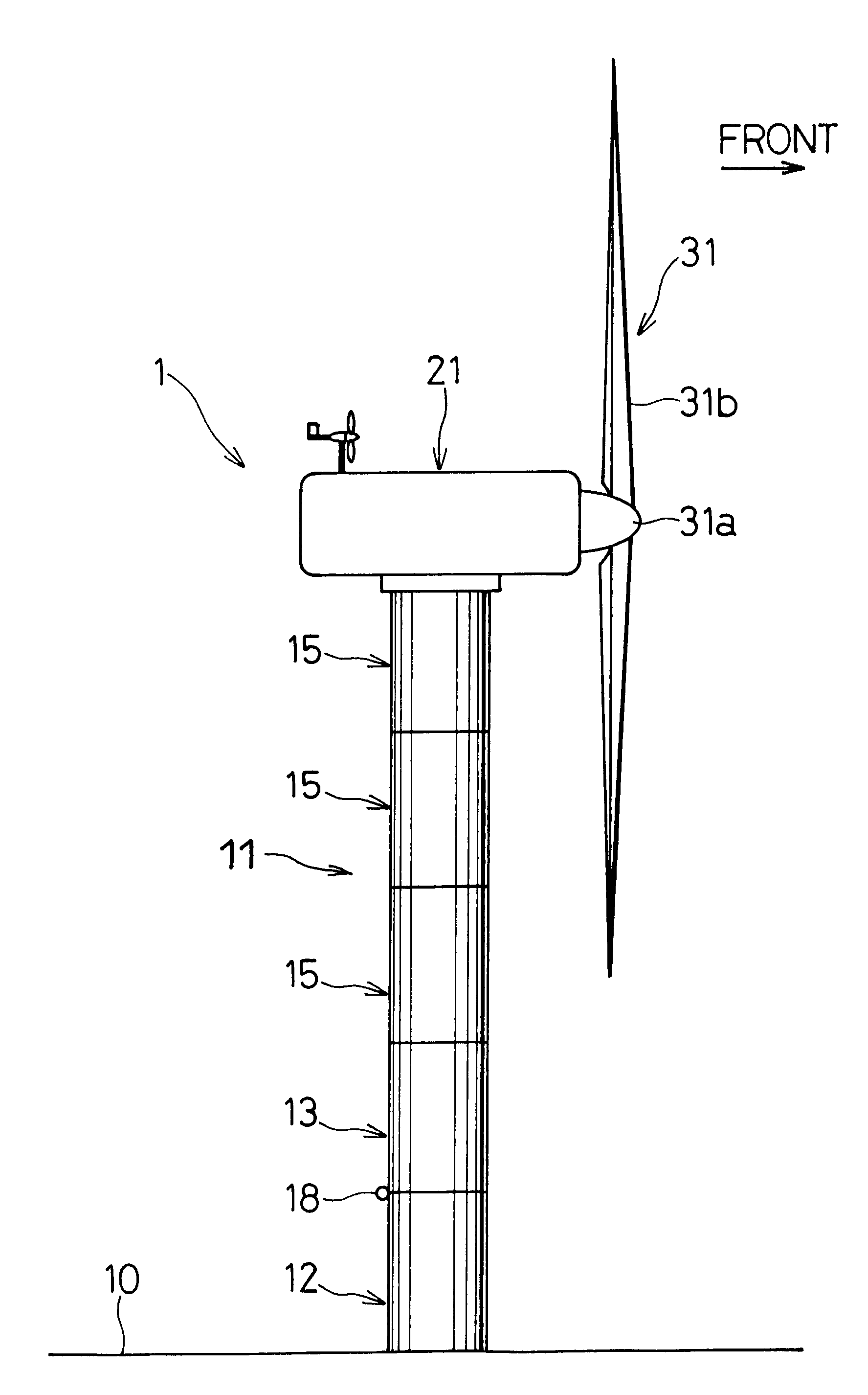
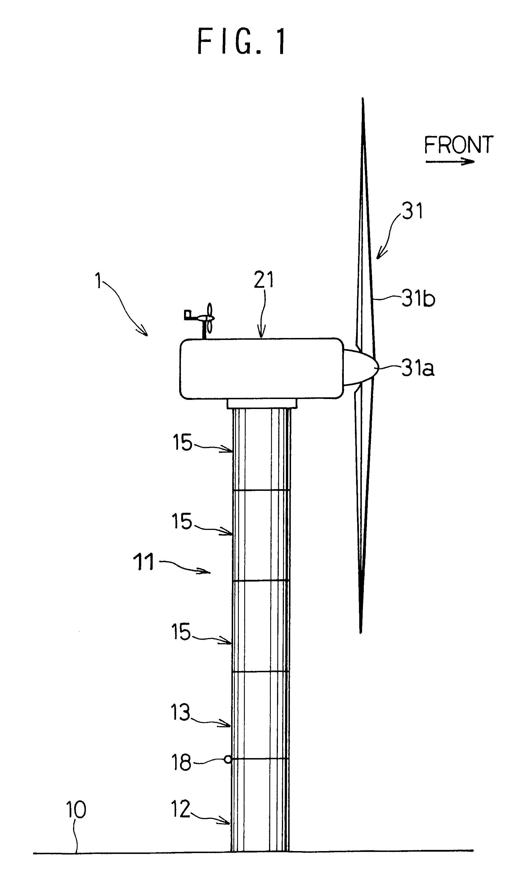
Referring now to FIG. 1, reference numeral 1 denotes a horizontal axis type wind turbine which comprises a base 10, a tower 11 standing on the base 10, a nacelle 21 mounted on the top end of the tower 11, a hub 31a supported by the nacelle 21, a rotor 31 including one or two blades 31b.

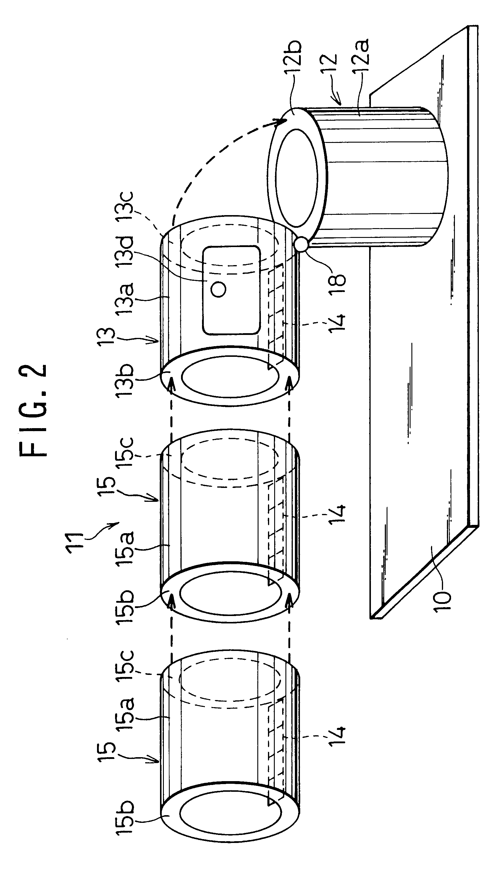
The tower 11 includes a base tower member 12 secured to the base 10, a lower tower member 13 and a plurality of connecting tower members 15.

The base tower member 12 is fabricated of metal and has a cylindrical or polygonal body 12a in which a man can work. An annular upper flange 12b is provided along the upper edge of the cylindrical body 12a with a peripheral edge folded inside. Further, there is provided a wire hole 12c which will be described hereinafter in the cylindrical body 12a.

Further, the lower tower member 13 is fabricated of metal and has a cylindrical body 13a with the same diameter as the cylindrical body 12a of the base tower member 12. The cylindrical body 13a has an annular upper flan...


PUM


Abstract

A tower comprises a base tower member fixed on a base in the ground, a lower tower member hingedly connected at a lower end thereof with an upper end of the base tower member through a hinge and swinging between a lying position and a standing position, a first stage connecting tower member connected at a lower end thereof with an upper end of the lower tower member, a second stage connecting tower member connected at a lower end thereof with an upper end of the first stage connecting tower member, and a third stage connecting tower member connected at a lower end thereof with an upper end of the second stage connecting tower member. Thus formed tower is raised swingingly around the hinge from the lying position to the standing position. A nacelle includes a tower penetrating hole through which the tower vertically penetrates and is formed by a plurality of nacelle sections divisible around the tower penetrating hole. After the tower is built, a plurality of nacelle sections are collected around the tower and are connected with each other while the nacelle is penetrated by the tower. Then, the nacelle is lifted up along the tower in that state and fixed to the top end of the tower.

Description

1. Field of the InventionThe present invention relates to a wind turbine, and more particularly, to a horizontal axis type wind turbine and a method of construction thereof.2. Background ArtIn general, the horizontal axis type wind turbine utilized for wind power generation, is installed on the top end of a tall tower so as to be able to acquire energy of natural wind efficiently.For example, a wind turbine of this kind is disclosed in Japanese Patent Application Laid-open No. Toku-Kai-Sho 58-192977. As shown in FIG. 10, the wind turbine comprises a base member 101, a tower 102 mounted on the base member 101 and vertically extending, a nacelle 103 supported at the top of the tower 102 and a rotor 104 installed in the nacelle 103.The tower 102 is hingedly connected with the base member 101 through a hinge 102a so as to swing between a standing position as illustrated in solid lines and a falling position as illustrated in two-dot chain lines. Further, a ginpole 106 is hingedly suppor...

Claims


Application Information

Patent Timeline
Patent Type & Authority Patents(United States)
IPC IPC(8): E04H12/34E04H12/00F03D11/04F03D11/00
CPCE04H12/34F03D11/04F05B2230/601Y02E10/728F05B2240/916Y02E10/726F05B2240/14F03D13/10F03D13/20Y02E10/72Y02P70/50
Inventor YOSHIDA, SHIGEOKAWAKITA, YUJIKOSHIOKA, YASUHIRONAGAO, TORUTAKAHASHI, NORIYUKI
Owner SUBARU CORP
Learn More