Pressure plate subassembly

a technology of pressure plate and sub-assembly, which is applied in the direction of mechanical actuator clutches, manufacturing tools, mechanical apparatus, etc., can solve the problems of pressure plate overheating, inadequate construction space,

Inactive Publication Date: 2002-06-25
ZF FRIEDRICHSHAFEN AG
View PDF16 Cites 27 Cited by
  • Summary
  • Abstract
  • Description
  • Claims
  • Application Information

AI Technical Summary

Problems solved by technology

In friction clutches of this type, there is a problem that the supply of cooling air into the interior of the clutch is limited, with the result that overheating of the clutch may occur, at least when the clutch is operated for a relatively long time with slip.
Furthermore, in this known friction clutch, there is the problem that sufficient construction space for the pivoting movement of the force accumulato

Method used


Image

  • Pressure plate subassembly
  • Pressure plate subassembly
  • Pressure plate subassembly

Examples


Embodiment Construction

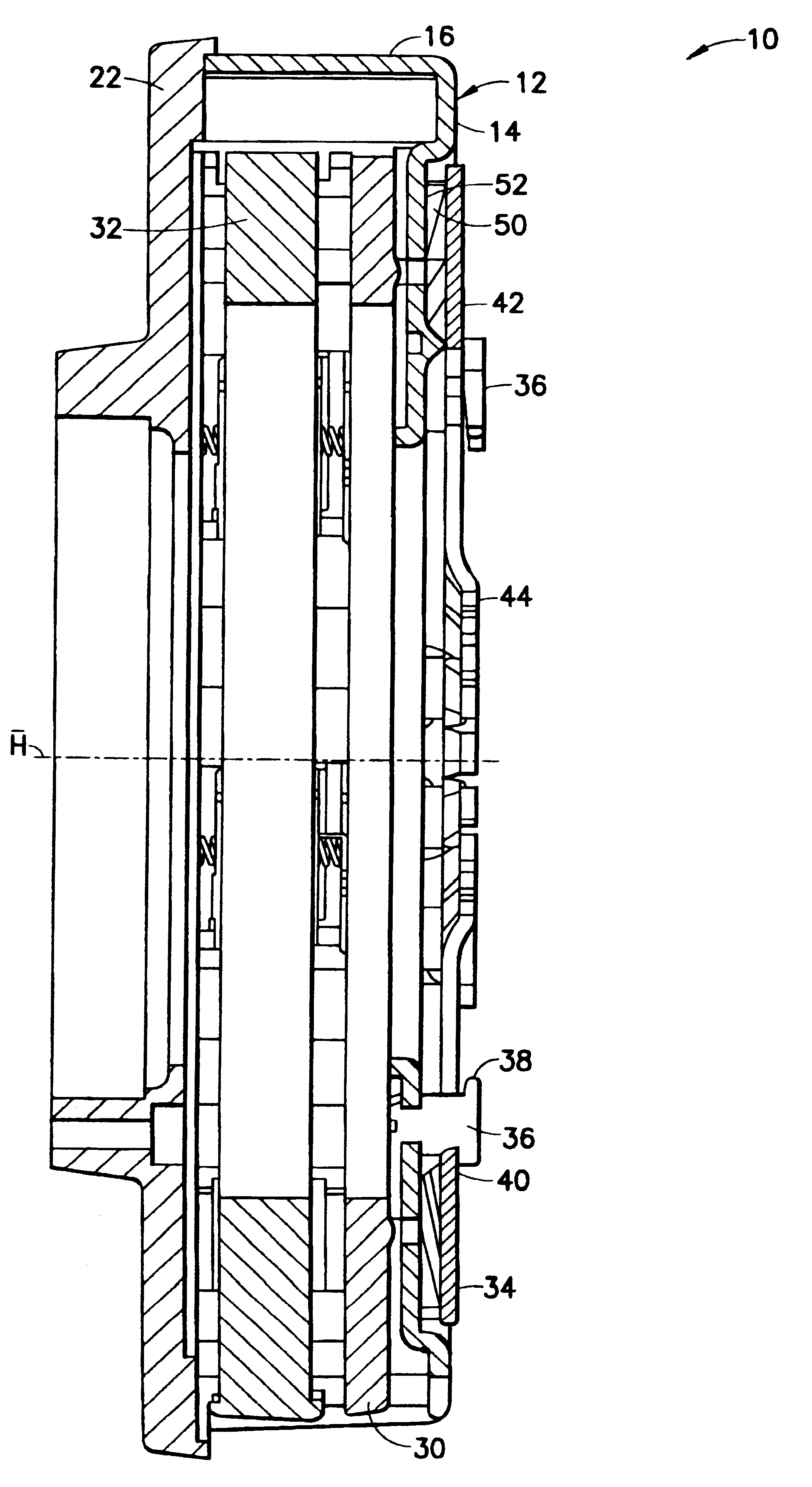
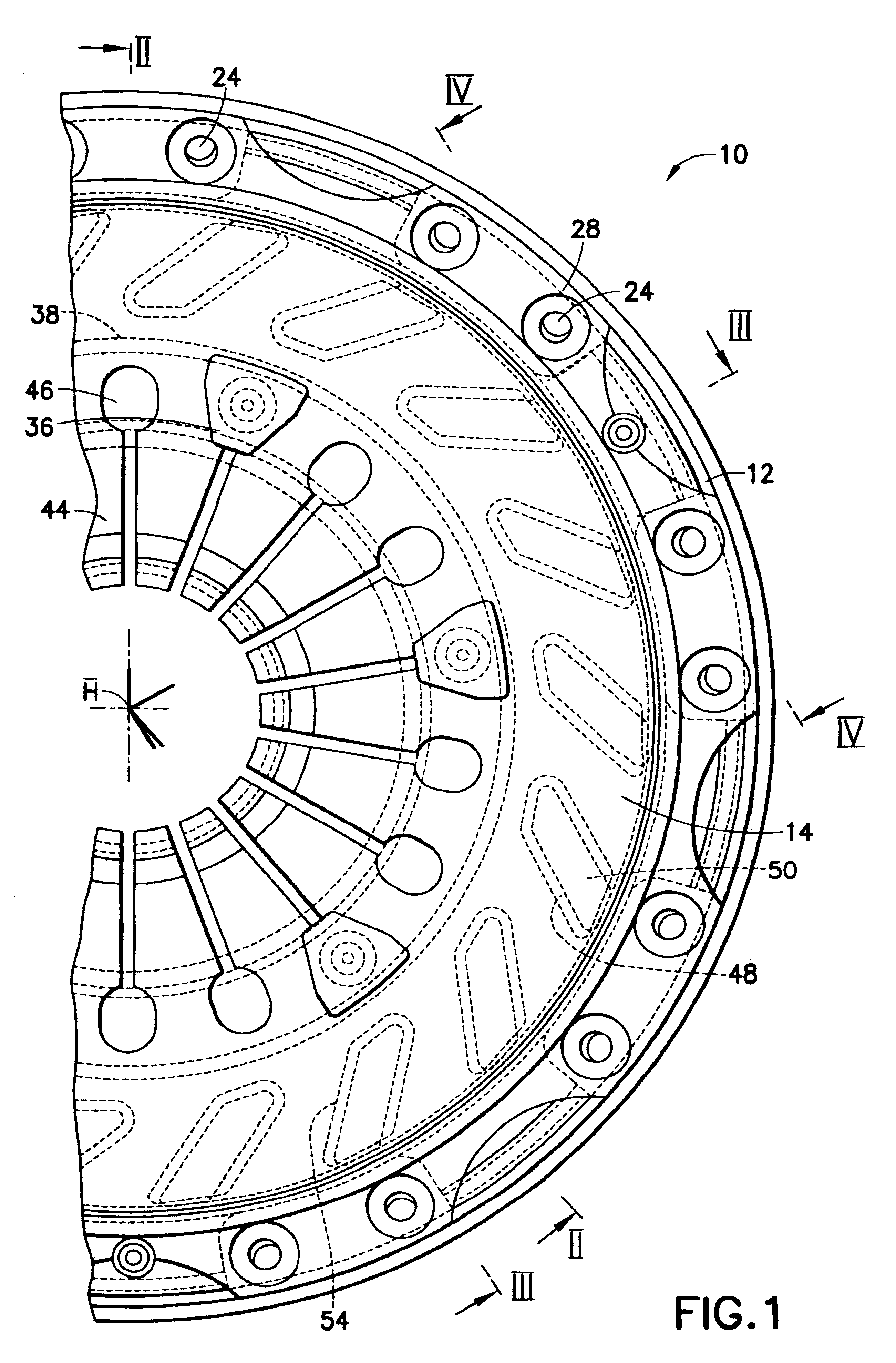
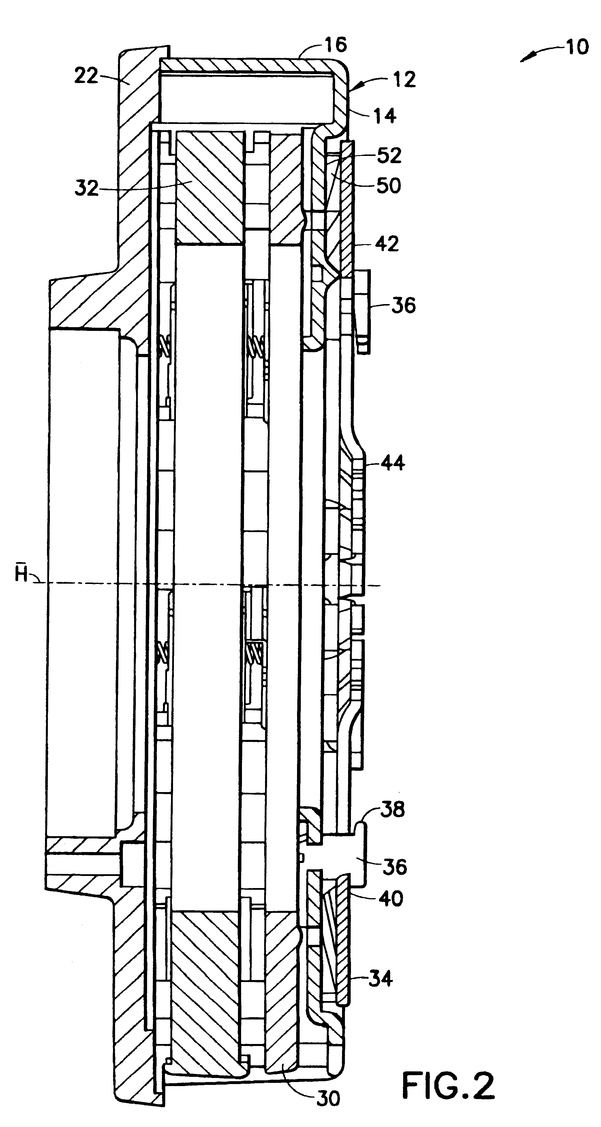
FIGS. 1-6 show a friction clutch 10 according to an embodiment of the present invention. The friction clutch 10 is designed as a multidisk clutch and comprises a clutch housing 12 having an approximately bowl-like design with a bottom region 14 and a wall region 16. The wall region 16 comprises web portions 18 arranged at a circumferential distance from one another along the circumferential direction. A recess 20 is formed between each adjacent pair of web portions. Screws or rivet bolts may be used to firmly connect the housing 12 via the web regions 18 to a flywheel 22 forming an abutment arrangement. For this purpose, the housing 12 has passage orifices 24 in the region of the webs through which the screws or rivet bolts may pass. The screws or rivet bolts may then be secured in threaded orifices or corresponding orifices 26 of the flywheel 22.

The housing 12 is preferably formed from a singular planar sheet metal blank. The recesses 20 may be produced by bending tab portions 28 w...


PUM

PropertyMeasurementUnit
Forceaaaaaaaaaa
Pressureaaaaaaaaaa
Distanceaaaaaaaaaa

Abstract

A pressure plate subassembly for a friction clutch includes a housing connectable to an abutment arrangement for joint rotation about an axis of rotation, a pressure plate arranged in the housing so that the pressure plate is rotatable together with the housing about the axis of rotation (A) and so that the pressure plate is displaceable relative to the housing in the direction of the axis of rotation, and a force accumulator for generating a pressure force, the force accumulator being supported on the housing and on the pressure plate. The force accumulator is arranged outside the housing.

Description

1. Field of the InventionThe present invention relates to a pressure plate subassembly for a multidisk friction clutch including a housing which is connectable or connected to an abutment arrangement for joint rotation about an axis of rotation, a pressure plate arranged in the housing so that the pressure plate is rotatable together with the housing and axially displaceable relative to the housing relative to the axis of rotation, and a force accumulator for generating a pressure force, the force accumulator being supported or supportable on the housing and on the pressure plate.2. Description of the Related ArtGerman reference DE 195 45 972 A1 discloses a multidisk friction clutch in which a plurality of clutch disks are designed in the form of lamellae connected to a common hub part. A pressure plate capable of being loaded by a force accumulator is provided in the clutch housing. Furthermore, a plurality of intermediate disks are connected fixedly in terms of rotation to the clu...

Claims


Application Information

Patent Timeline
IPC IPC(8): F16D13/71F16D13/58F16D13/52F16D13/00F16D13/38F16D13/69
CPCF16D13/385F16D13/52F16D13/71Y10T29/49844F16D2013/706Y10T29/49849F16D2013/581
Inventor ORLAMUNDER, ANDREASLINK, ACHIMREIBER, WOLFGANGVOGT, SEBASTIAN
Owner ZF FRIEDRICHSHAFEN AG
Why Eureka
Try Eureka