
Video system for three dimensional imaging and photogrammetry

a three-dimensional imaging and video system technology, applied in the field of three-dimensional imaging and photogrammetry, can solve the problems of inability to sterilize handpieces, affecting the operation of inter-oral cameras, and requiring the use of impediment-resistant plastic enclosures,

Inactive Publication Date: 2002-07-02
DENTOP SYST
View PDF4 Cites 122 Cited by
  • Summary
  • Abstract
  • Description
  • Claims
  • Application Information

AI Technical Summary

Benefits of technology

A feature of a preferred embodiment of the present invention is the use of a video system placed outside of the oral cavity of the patient, thus allowing the dentist unobstructed access to the oral cavity.
Another object of the present invention is to provide a video system for producing a composite video image composed of three different superimposed video images, each of the three video images taken from a different angle of view. The composite video image can be fed to a host computer for performing various photogrammetric measurements thereon, thus obviating the use of a photogrammetric still camera and the processing of the film.
A feature of a preferred embodiment of the present invention is that the video system which is used for providing a three dimensional video image of the oral cavity, can also be used for providing a composite video image for photogrammetric measurements, thus obviating the need for a separate photogrammetric camera.

Problems solved by technology

Unfortunately, inter-oral cameras need to be sterilized before each use.
The camera and the handpiece cannot be sterilized, thus forcing the use of impeding sterilizable plastic enclosures, an expensive and time consuming procedure.
Additionally, inter-oral cameras lack zooming capacity due to the limited possible size of the lens.
Some IOC's have a limited capacity for up to three different magnification levels but no continuous zooming capacity.
Furthermore, the large size of the handpiece and the power-cord of inter-oral cameras is obstructive to the practitioner performing dental work.
In this arrangement, however, the surgeon does not see the real world, but sees only the image displayed on the video screens directly in front of his eyes.
This method requires precision manual photogrammetric measurement and calibration techniques which are time consuming, expensive and which requires considerable expertise.
Additionally, prior art of photogrammetric measurement of implant positions requires developing the film before measurements can be performed, adding to the cost and duration of the procedure.

Method used


Image

  • Video system for three dimensional imaging and photogrammetry
  • Video system for three dimensional imaging and photogrammetry
  • Video system for three dimensional imaging and photogrammetry

Examples


Embodiment Construction

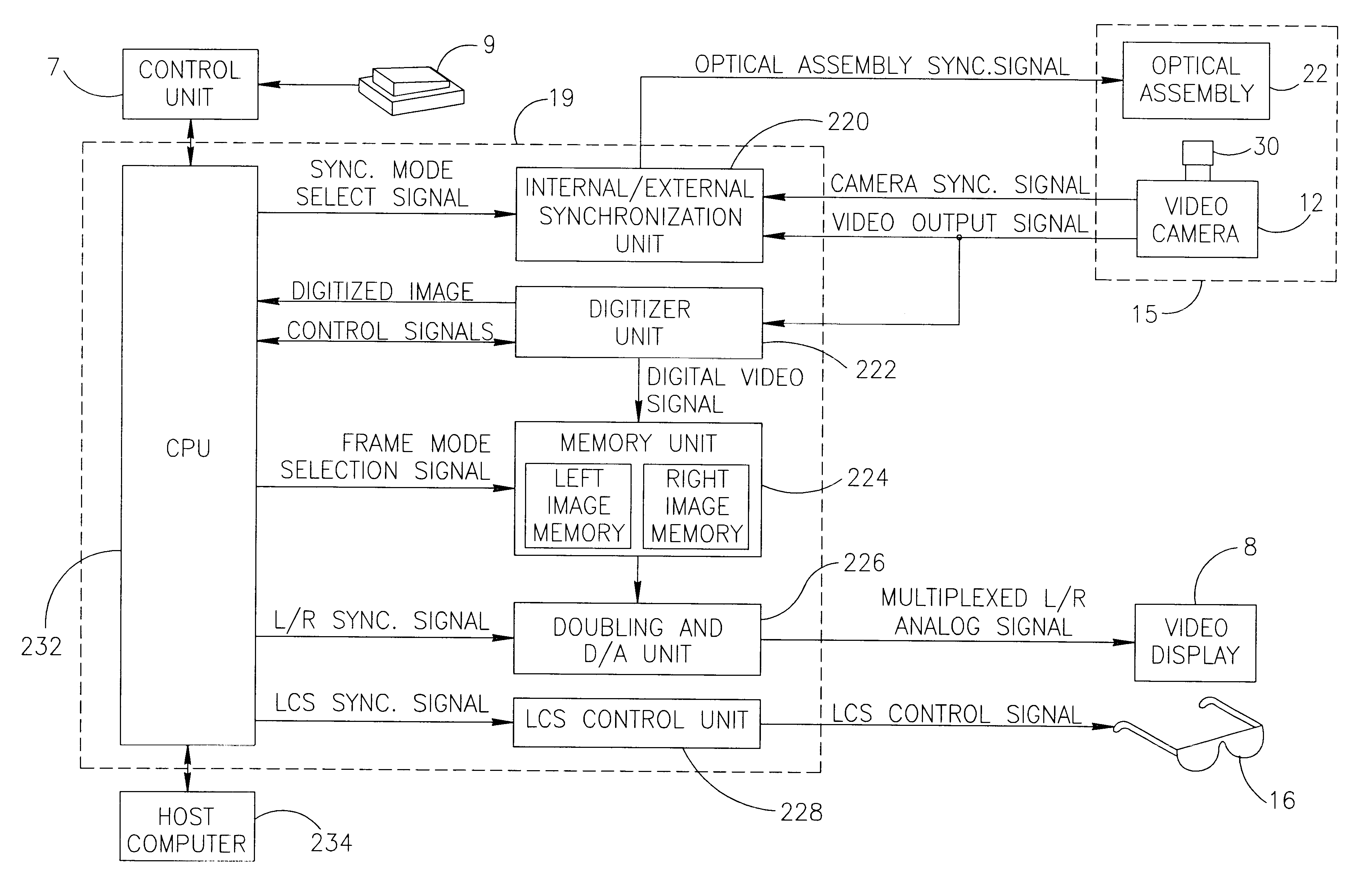
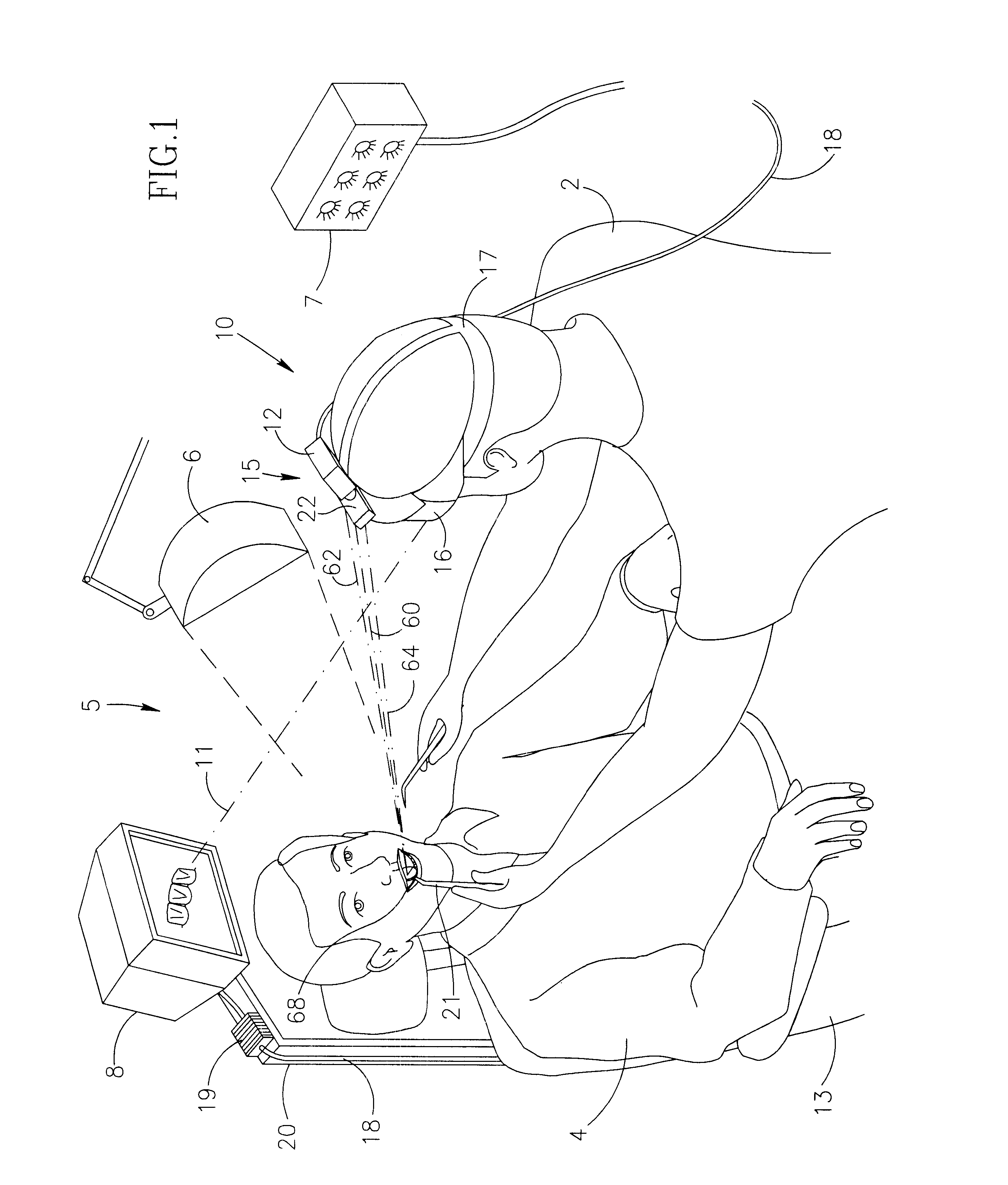
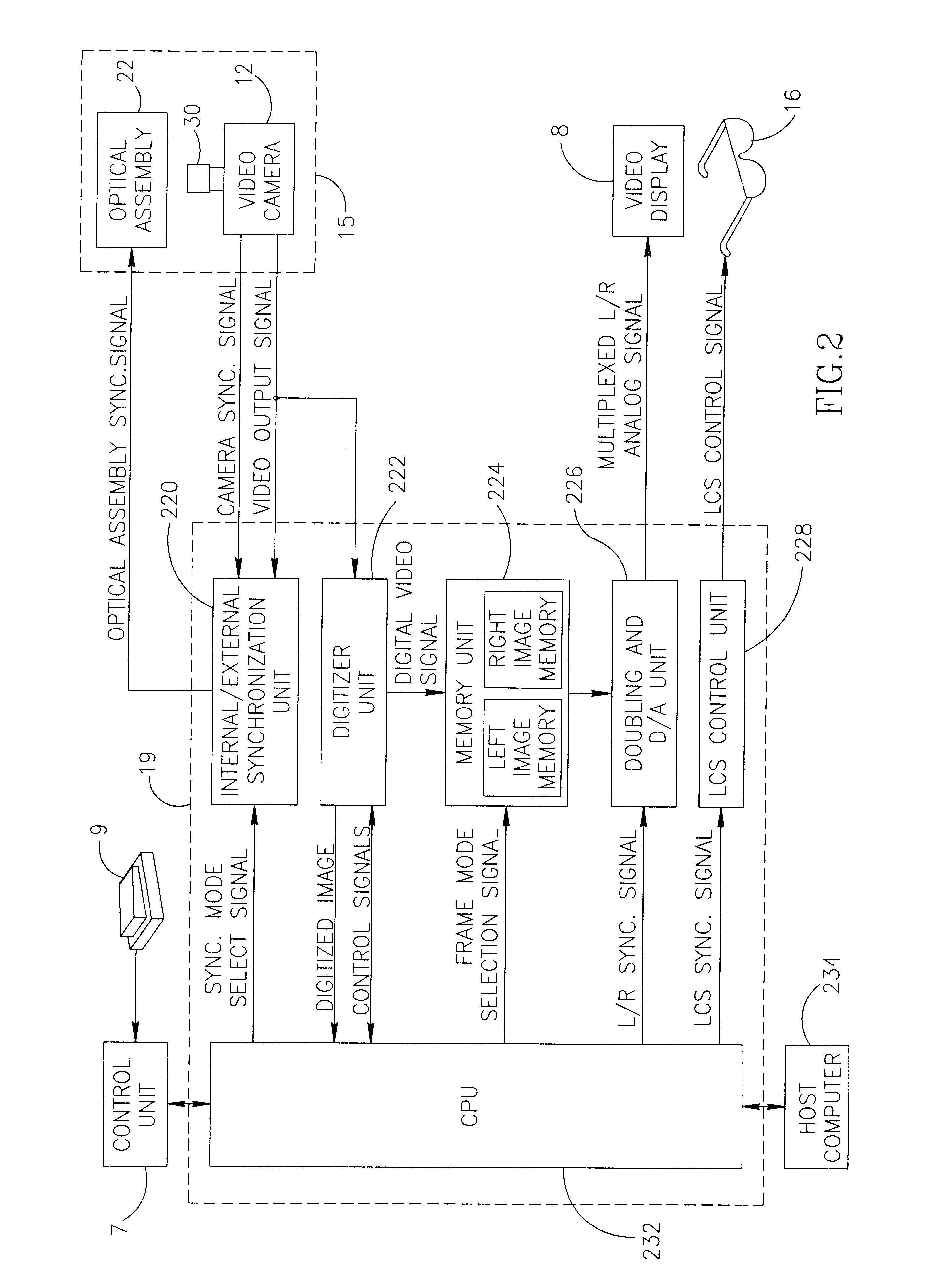
Reference is now made to FIG. 1 which is an isometric view of a three dimensional (3D) stereoscopic video system, generally referred to as video system 5 hereinafter, for 3D viewing and for photogrammetric video photography. The system 5 is capable of providing 3 different angular views of a viewed object in accordance with a preferred embodiment of the present invention. The video system 5 is shown as used by a dentist 2 while working on a patient 4. The video system 5 includes a headset 10 worn on the head of the dentist 2 for providing three dimensional imaging capability. The video system 5 also includes a video display 8 supported by display stand 20 for displaying a video image of the oral cavity 68. The display stand 20 is attached to a chair 13. Patient 4 sits on the chair 13 while being treated by the dentist 2. It is noted that the video display 8 can also be positioned at any suitable position such as above the head of the patient 4 or at the side of the patient 4.

The hea...


PUM


Abstract

A video system for providing an operator with a three dimensional stereoscopic image of the oral cavity of a patient is provided. The system includes an imaging unit for providing at least two stereoscopic images of the oral cavity, a pair of switchable shutters for alternatingly blocking the view of the left eye and the right eye of the operator, a synchronizing unit for synchronizing the switching of the pair of switchable shutters with the rate of generation of the two stereoscopic video images by the imaging unit and a video display for displaying the two stereoscopic images.

Description

The present invention relates to the field of three dimensional imaging in general, the field of three dimensional (3D) video imaging in particular and specifically to three dimensional imaging systems for dentistry.The use of video cameras in dentistry is a well known in the prior art. Different types of video cameras are used by dentists for viewing the oral cavity, magnifying the view thereof and for recording video images of the oral cavity or selected parts thereof.Dentists routinely use an inter-oral camera (IOC) inserted into the patients mouth for inter-oral photography. An IOC is usually used in teeth implantation for obtaining exact video photographs used for the precise measurements and three dimensional reconstruction needed for preparing the rehabilitation infrastructure.Unfortunately, inter-oral cameras need to be sterilized before each use. The camera and the handpiece cannot be sterilized, thus forcing the use of impeding sterilizable plastic enclosures, an expensive...

Claims


Application Information

Patent Timeline
IPC IPC(8): A61B1/00A61B1/24G02B27/22H04N13/00A61B1/045H04N13/239
CPCA61B1/00045A61B1/00048A61B1/00193A61B1/24G02B27/2264H04N13/0048H04N13/0051H04N13/021H04N13/0239H04N13/0296H04N13/0438H04N13/0497A61B1/045A61B1/06H04N13/0055H04N13/0246H04N13/341H04N13/167H04N13/211H04N13/189H04N13/246H04N13/161H04N13/296H04N13/239H04N13/398G02B30/24A61B1/00194
Inventor CARMELI, RANDADI, MICHEL
Owner DENTOP SYST
Learn More