Handle for adjustable hitch head assembly

a technology of adjustable handle and adjustable head, which is applied in the direction of wing knobs, furniture parts, manufacturing tools, etc., can solve the problems of difficulty in manually transporting when not being used, serious back injuries of the person carrying etc., and achieves the effect of easy lifting and balanced, easy transportation, and increased mobility of the hitch head assembly

Inactive Publication Date: 2002-07-09
DIXON RICHARD W
View PDF16 Cites 12 Cited by
  • Summary
  • Abstract
  • Description
  • Claims
  • Application Information

AI Technical Summary

Benefits of technology

The present invention, referred to herein as a "hitch handle", attaches to the top or other hole in the adjustable hitch bar portion of the hitch head assembly in a fashion that renders the assembly easily lifted and balanced in one hand, which increases the mobility of the hitch head assembly. The hitch handle is thus designed so that the hitch head assembly is easily balanced for transportation. This feature enables the person attaching, transporting or detaching the assembly to be less encumbered during the process and produces less stress on the lower back.
The hitch handle thus "hooks" into the top hole of the adjustable hitch bar to form an extension that fits easily in the hand. This extended part may be covered with a soft frictional material to improve the gripping capability. Although the hitch head assembly may be carried with either end at the front of the person carrying the hitch head assembly, it is more comfortable to have the assembly at the side and the remainder of the assembly to the rear. The hitch handle thus balances the hitch head assembly to reduce the awkwardness of carrying the assembly.

Problems solved by technology

Hitch head assemblies are cumbersome in design and construction, rendering them difficult to manually transport when they are not being used.
Due to the weight, the person carrying the hitch head assembly may suffer serious injury to the back in bending and lifting the hitch head assembly.

Method used


Image

  • Handle for adjustable hitch head assembly
  • Handle for adjustable hitch head assembly
  • Handle for adjustable hitch head assembly

Examples


Embodiment Construction

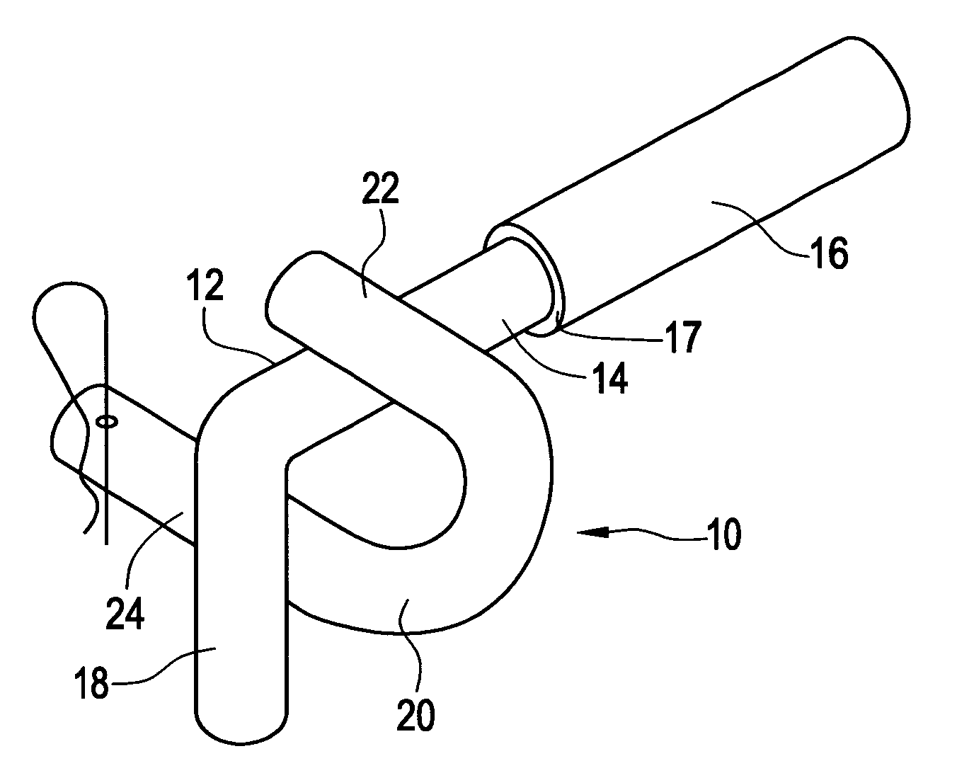
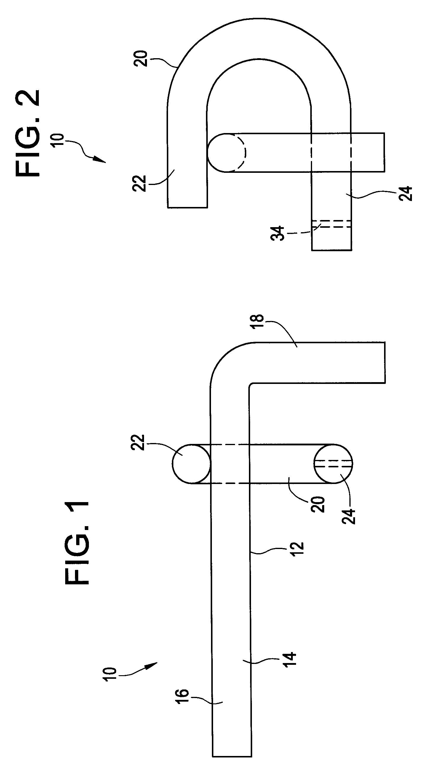
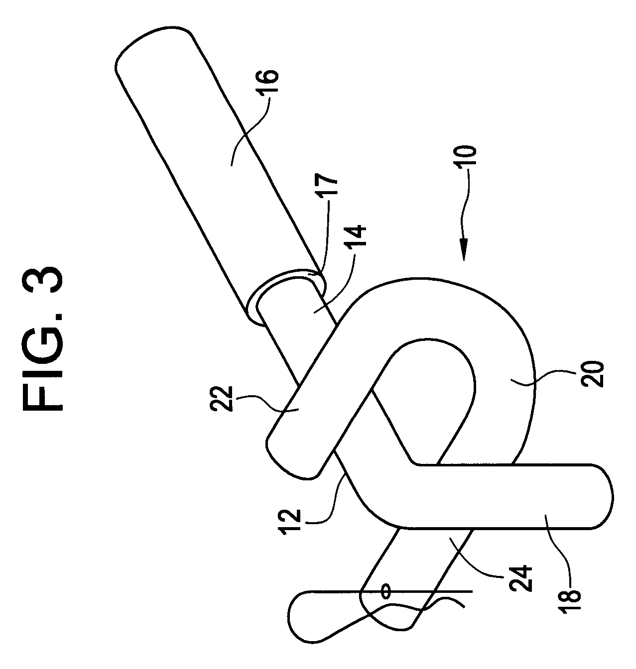
As best seen in FIGS. 1 and 2 the hitch handle 10 of the present invention includes an L-shaped portion 12, the elongated leg 14 of which extends in a direction so that in use it may form a hand grasp 16. As seen for example in FIG. 3, the hand grasp 16 can comprise a soft frictional material 17 such as rubber, plastic or the like. The shortened leg 18 of the L-shaped portion is designed to bear against a portion of the hitch head assembly.

A U-shaped member 20 has a first leg 22 which is secured to the elongated leg 14 of the L-shaped portion 12. The securing can be effected by welding or by other connecting methods, either mechanical or otherwise. Or it is possible to form the entire handle 10 from a single piece, as for example by a molding or other procedure. The U-shaped member 20 is seen to be in a plane transverse to the plane of the L-shaped portion 12. The second leg 24 of U-shaped member 20 is removably receivable in one of the openings 26 (FIG. 3) in the adjustable hitch b...


PUM


Abstract

A hitch handle for engaging and facilitating carrying of a hitch head assembly of the type which includes a substantially vertically extending adjustable hitch bar having one or more circular openings. The handle has an L-shaped portion, the elongated leg of which forms a hand grasp for the user and the shortened leg of which extends in a direction to in use bear against a part of the hitch bar. The front leg of the U member is secured to the elongated leg of the L-shaped portion, the U member being in a plane transverse to the plane of the L-shaped portion. The second leg of the U-shaped member is removably receivable in an opening in the substantially vertical hitch bar. Upon the second leg of the U being so received, an upward force supplied by the user at the hand grasp rotates the L around the axis defined by the second leg of the U to bring the shorter leg to bear against the hitch head assembly, thereby frictionally locking the handle against further rotation and enabling balanced lifting of the hitch head assembly by the user.

Description

This invention relates to an apparatus which when attached to an adjustable hitch head assembly can be used to facilitate the installation, removal and transport of the hitch head assembly. The invention, referred to herein as a "hitch handle", is constructed of a material that can withstand the weight of the trailer hitch head assembly, which can be in excess of 50 pounds. Although the material of construction can be a polymeric composite material such as a glass filled nylon, the preferred material of construction is a strong durable metal such as iron, stainless steel, etc.BACKGROUND OF INVENTIONHitches are used to connect trailers such as mobile homes, travel trailers, horse trailers, motorcycle trailers and the like to a vehicle, which will then tow the connected ensemble to the desired location. Hitch head assemblies are cumbersome in design and construction, rendering them difficult to manually transport when they are not being used. Hitch head assemblies are heavy as they ar...

Claims


Application Information

Patent Timeline
Patent Type & Authority Patents(United States)
IPC IPC(8): B60D1/00B60D1/14B60D1/07B60D1/46
CPCB60D1/00B60D1/07B60D1/14B60D1/46Y10T16/509Y10T16/469Y10T16/4707Y10T16/44Y10T16/498B60D2001/006
Inventor DIXON, RICHARD W.
Owner DIXON RICHARD W
Why Eureka
Try Eureka