Electronic drive systems and methods

a technology of electronic drive and drive shaft, applied in the direction of printing, other printing apparatus, etc., can solve the problem of suction of ink into

Inactive Publication Date: 2002-07-16
XEROX CORP +1
View PDF14 Cites 25 Cited by
  • Summary
  • Abstract
  • Description
  • Claims
  • Application Information

AI Technical Summary

Problems solved by technology

The drop-on-demand drive method makes it unnecessary to recover ink not needed for recording.
This result in suction of ink into an ink ejection chamber.

Method used


Image

  • Electronic drive systems and methods
  • Electronic drive systems and methods
  • Electronic drive systems and methods

Examples


Embodiment Construction

The systems and methods of this invention will be described below with reference to an electrostatically actuated fluid ejector as described in copending U.S. patent application Ser. Nos. 09 / 718,420 and 09 / 722,331, each of which is incorporated herein by reference in its entirety. It should be understood, however, that the systems and methods of this invention may be applied to a wide variety of devices other than the specific embodiment of the fluid ejector discussed below or fluid ejectors in general.

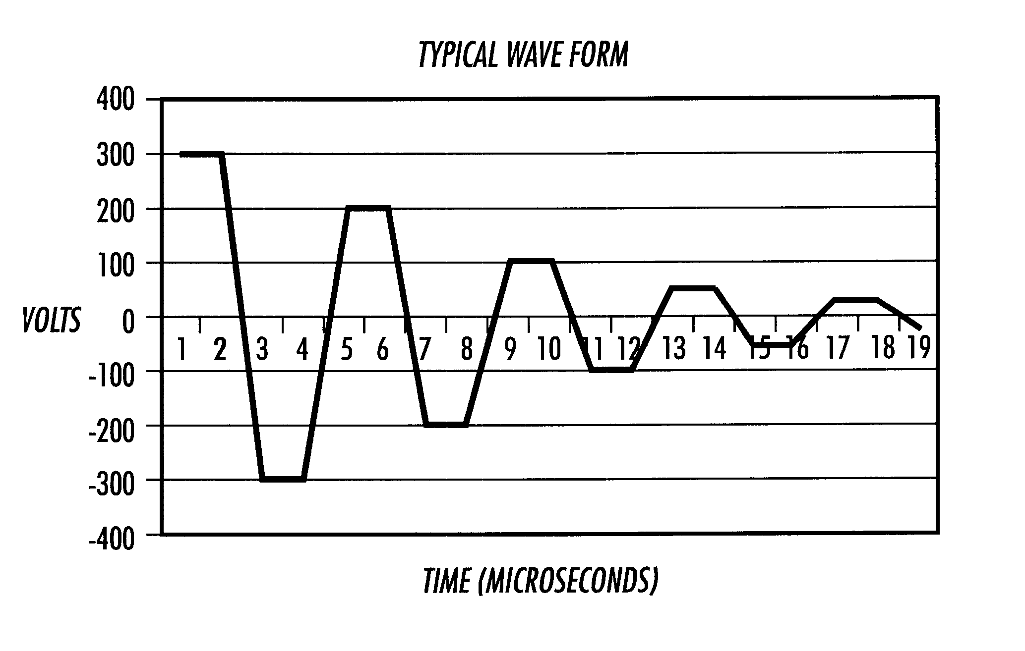
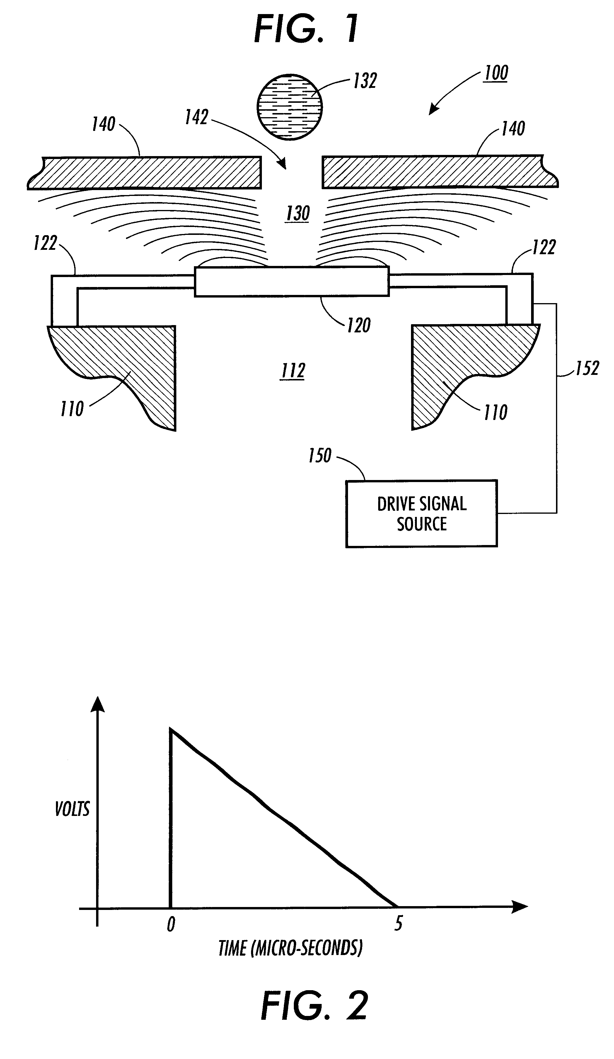
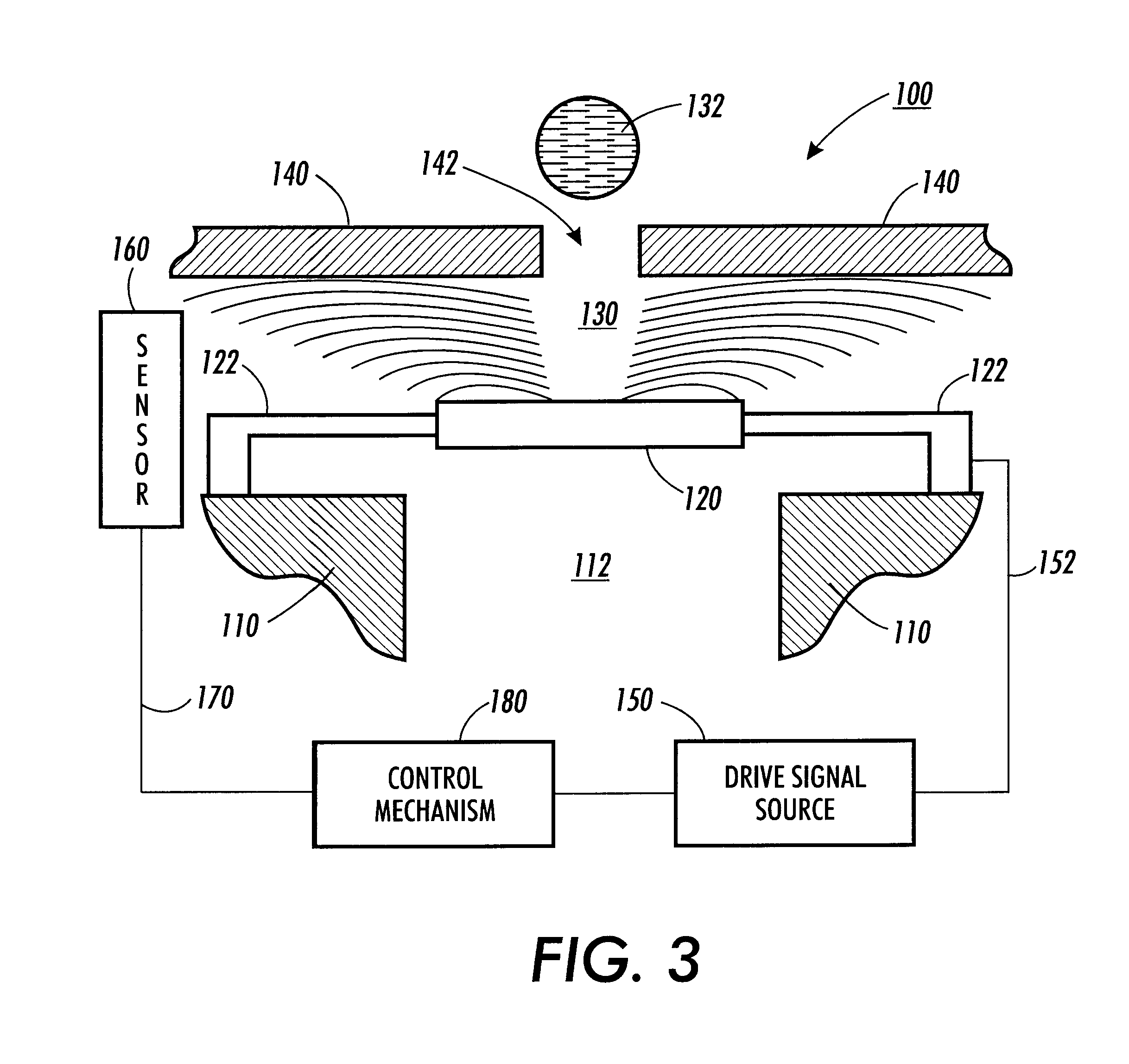
In various exemplary embodiments of the systems and methods according to this invention, a drive signal is applied to an electrostatically actuated device such that a resulting electric field has a constant force. For example, in an electrostatically actuated fluid ejector, the drive signal is applied to one of a piston and a faceplate including a nozzle hole. A dielectric fluid to be ejected is supplied between the piston and the faceplate. The drive signal generates an electric fiel...


PUM


Abstract

An electronic drive system applies a drive signal to an electrostatically actuated device such that a resulting electric field has a constant force. In various exemplary embodiments, the electronic drive system applies a drive signal to an electrostatically actuated fluid ejector that has a piston and a faceplate including a nozzle hole. A dielectric fluid to be ejected is supplied between the piston and the faceplate. The drive signal is applied to one of the piston and the faceplate. The drive signal generates an electric field across the fluid between the piston and the faceplate. The electric field causes the piston to be electrostatically attracted towards the faceplate so that a jet or drop of fluid is ejected through the nozzle hole of the faceplate. According to exemplary embodiments, the drive signal is from a constant current source or is reduced over the course of its lifetime. Further, according to various exemplary embodiments, the drive signal is of a suitable high frequency to reduce the potential of electrochemical reactions or electrical breakdown, or both. The drive signal may also be a bi-polar drive signal to reduce the possibility of electrochemical reactions.

Description

1. Filed of the InventionThis invention relates to systems and methods for driving an electrostatically actuated device using an electronic drive signal.2. Description of the Related ArtOne type of electrostatically actuated device with which the systems and methods of this invention may be used is micromachined fluid ejectors. Fluid ejectors have been developed for ink jet recording or printing, as well as other uses. Ink jet recording apparatus offer numerous benefits, including extremely quiet operation when recording, high speed printing, a high degree of freedom in ink selection, and the ability to use low-cost plain paper. The so-called "drop-on-demand" drive method, where ink is output only when required for recording, is now the conventional approach. The drop-on-demand drive method makes it unnecessary to recover ink not needed for recording.Fluid ejectors, including those used for ink jet printing, include one or more nozzles that allow the formation and control of small i...

Claims


Application Information

Patent Timeline
Patent Type & Authority Patents(United States)
IPC IPC(8): B41J2/14B41J2/045B41J2/055
CPCB41J2/14B41J2002/043
Inventor GOORAY, ARTHUR M.ROLLER, GEORGE J.CROWLEY, JOSEPH M.GALAMBOS, PAUL C.PETER, FRANK J.ZAVADIL, KEVIN R.GIVLER, RICHARD C.LINDENFELSER, WILLIAM M.
Owner XEROX CORP
Why Eureka
Try Eureka