Multiple beam laser marking apparatus

a laser marking and multi-beam technology, applied in the direction of digitally marking record carriers, instruments, manufacturing tools, etc., can solve the problems of not being able to meet the requirements of patent specifications, the size of individual lasers is not readily available,

Inactive Publication Date: 2002-07-16
DOMINO THE
View PDF8 Cites 69 Cited by
  • Summary
  • Abstract
  • Description
  • Claims
  • Application Information

AI Technical Summary

Benefits of technology

By this means the resulting optical system can produce a plurality of marks properly spaced to produce alpha-numeric, graphic and / or machine-readable marks on moving substrates whilst providing a very compact system which can be fitted in relatively small spaces typically provided on production lines and the like.

Problems solved by technology

One of the main problems in building a compact and commercially viable laser marking system utilising multiple laser channels, is to position the laser channels in such a manner as to reduce the physical size of the channel assembly whilst simultaneously simplifying the optical configuration necessary to provide the required optical marking characteristics.
In general, the physical size of individual lasers does not readily allow one to obtain simultaneously the optical spacing and angular relationships between the laser required for optimum optical performance.
However, the above patent specification does not deal with the problem of providing a suitably small character size from multiple dots.

Method used


Image

  • Multiple beam laser marking apparatus
  • Multiple beam laser marking apparatus
  • Multiple beam laser marking apparatus

Examples


Embodiment Construction

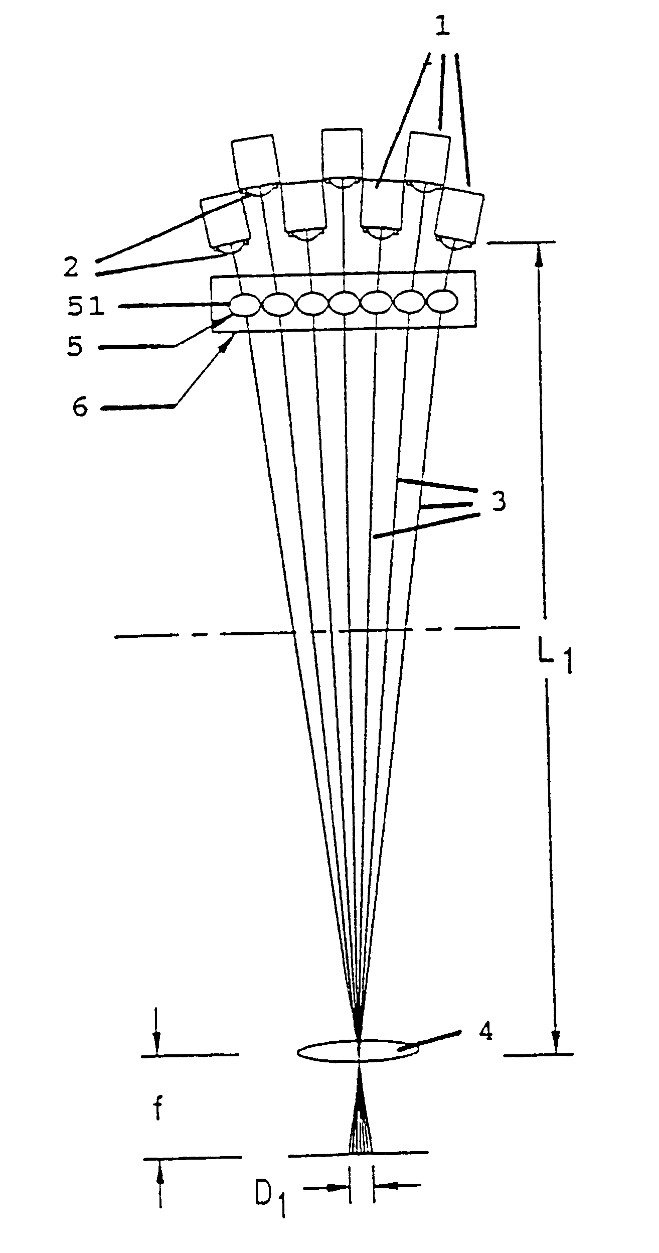
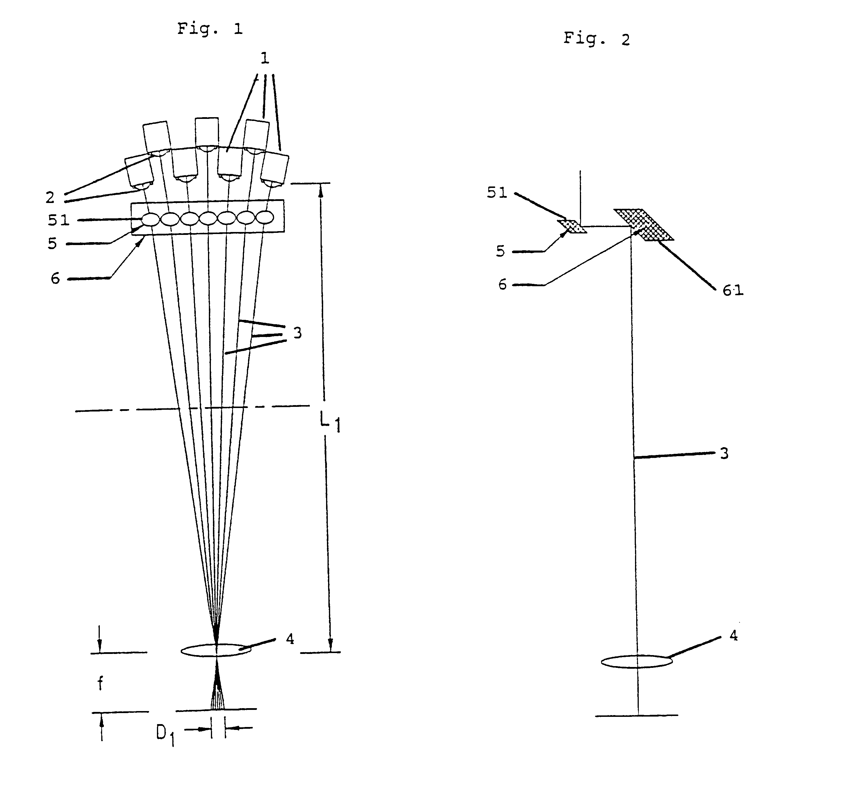
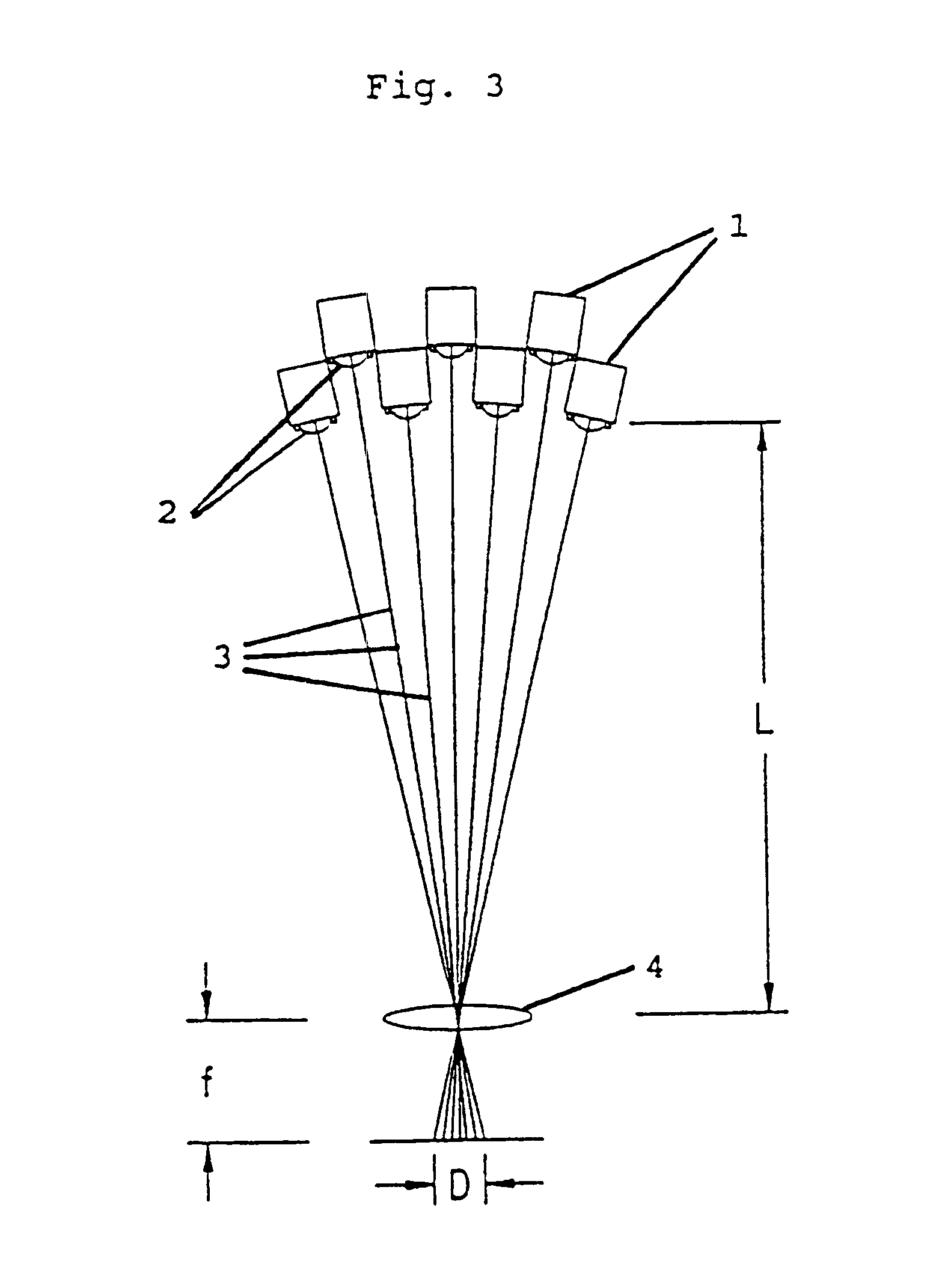
In order to produce a compact laser marking or coding device, individual lasers 1 are closely located with their respective output ends 2 disposed adjacent to one another and in a staggered, overlapping relationship as shown in FIGS. 1 and 3. As shown in FIG. 3, the resulting angles between the respective laser beams 3 cause the beams, once they have been passed through the usual focusing lens 4, to be spaced apart from one another over a total distance D at an appropriate distance f from the lens 4. This may be too large for many marking applications.

FIGS. 1 and 2, by comparison with FIG. 3, show how plural mirror assemblies 5, 6 can be used to extend the overall path of the laser beams 3 from L to L.sub.1, at the same time reducing the angle between the respective laser beams 3 and thus producing a set of beams which have a total separation distance D.sub.1 which is considerably less than the total separation D of the apparatus shown in FIG. 3. The first re-directing mirror assemb...


PUM

PropertyMeasurementUnit
reflection anglesaaaaaaaaaa
separation angleaaaaaaaaaa

Abstract

A laser marking apparatus has a number of individual laser devices (1) mounted at angles to one another. The output ends (2) of the laser devices are disposed closely adjacent to one another and a number of laser beam redirectors (5) are disposed to intercept the laser beams (3) emitted from the laser output ends (2) so as to extend the length of the laser beam paths and to decrease the angle between said laser beams (3).

Description

The present invention relates to lasers and, more particularly, to the optics of a laser system for use in marking and coding applications.Background of the InventionLasers suitable for use in such applications have been described in U.S. Pat. No. 4,618,961, U.S. Pat. No. 4,891,819 and U.S. Pat. No. 5,095,490. Additionally, in U.S. Pat. No. 4,652,722 there is described a laser apparatus utilising a plurality of coherent laser beams in conjunction with fixed reflecting means, beam tubes and a focusing lens, to providing marking indicia or permanent alteration of substrate surfaces. Claim 1 of U.S. Pat. No. 4,652,722 is directed to features which enable the optical path to be shortened and the specification describes how the optical path can be shortened using the reflecting means.One of the main problems in building a compact and commercially viable laser marking system utilising multiple laser channels, is to position the laser channels in such a manner as to reduce the physical siz...

Claims


Application Information

Patent Timeline
Patent Type & Authority Patents(United States)
IPC IPC(8): G06K1/00G06K1/12B23K26/06B23K26/00H01S3/00
CPCG06K1/126
Inventor SUTTER, LEROY V.BLACKBURN, RICHARD
Owner DOMINO THE
Why Eureka
Try Eureka