Apparatus and method for efficient conversion of DV (digital video) format encoded video data into MPEG format encoded video data by utilizing motion flag information contained in the DV data

Inactive Publication Date: 2002-07-16
PANASONIC CORP
View PDF14 Cites 87 Cited by
  • Summary
  • Abstract
  • Description
  • Claims
  • Application Information

AI Technical Summary

Problems solved by technology

However progressive-field mode processing results in a greater amount of code being generated th

Method used


Image

  • Apparatus and method for efficient conversion of DV (digital video) format encoded video data into MPEG format encoded video data by utilizing motion flag information contained in the DV data
  • Apparatus and method for efficient conversion of DV (digital video) format encoded video data into MPEG format encoded video data by utilizing motion flag information contained in the DV data
  • Apparatus and method for efficient conversion of DV (digital video) format encoded video data into MPEG format encoded video data by utilizing motion flag information contained in the DV data

Examples


first embodiment

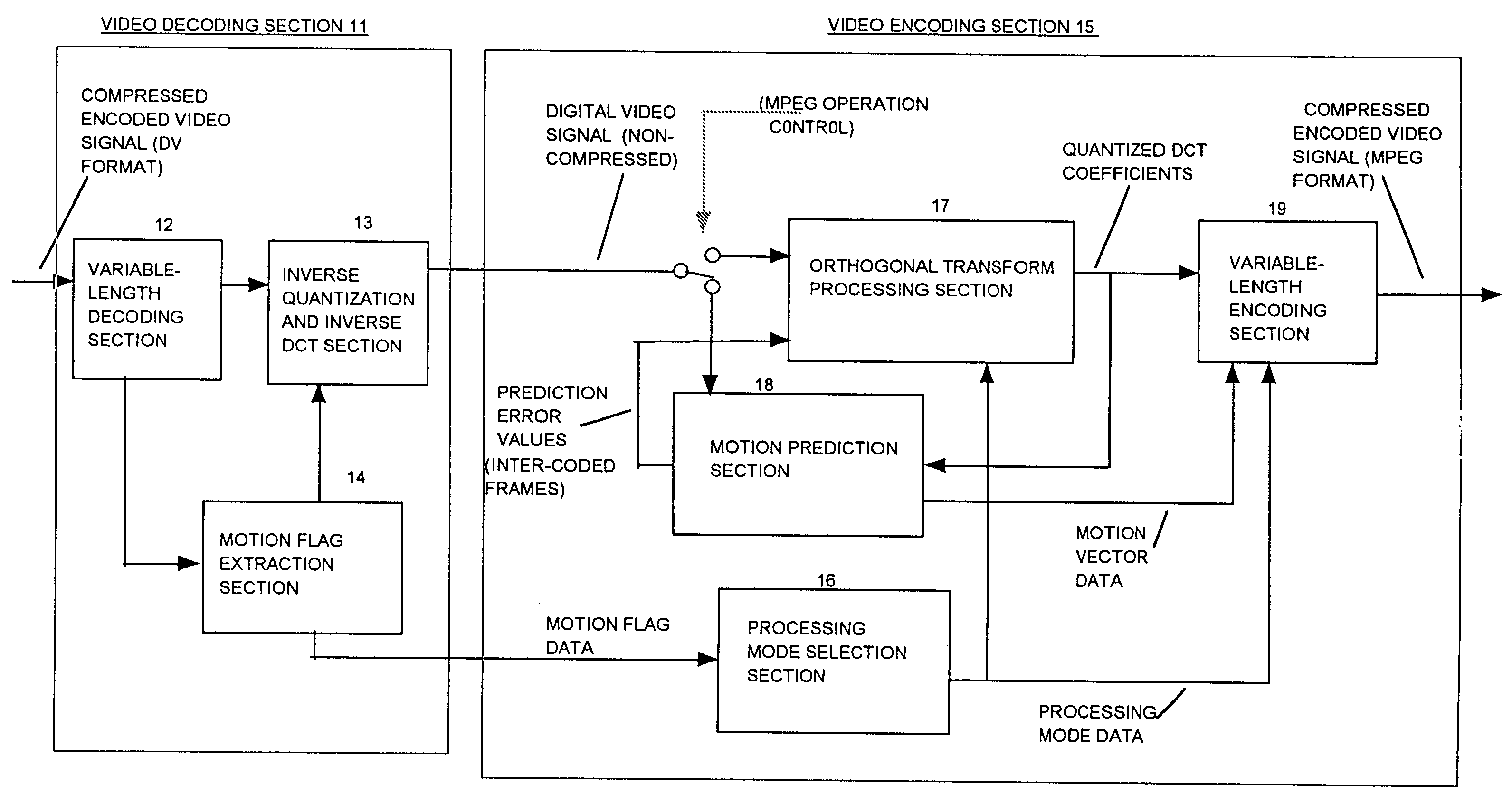
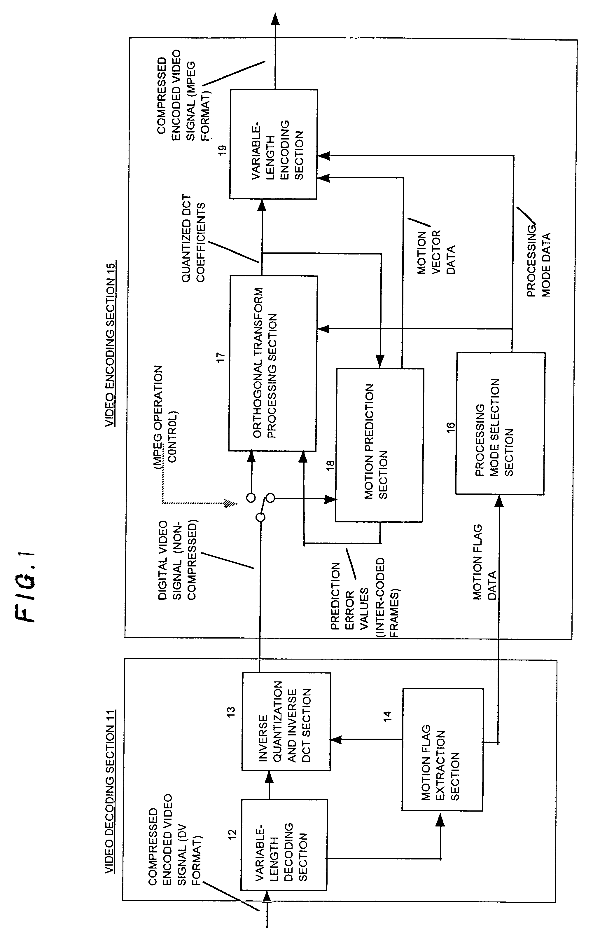
FIG. 1 is a general system block diagram showing a first embodiment of a video signal conversion apparatus according to the present invention. With this embodiment, the DCT processing which is executed as part of MPEG encoding is adaptively changed between interlaced-field mode processing and progressive-field mode processing, in accordance with the motion flag data obtained from the DV encoded data. With interlaced-field mode DCT processing, each 8.times.8 value DCT block is made up of values obtained from 8 successive lines of an interlaced-field frame, while with progressive-field mode DCT processing, each DCT block is obtained from only the odd-numbered or only the even-numbered lines of an interlaced-field frame, i.e. from the first field or from the second field of that frame. Adaptive selection of interlaced-field mode DCT processing or progressive-field mode DCT processing is executed in units of macroblocks.

In FIG. 1, a video decoding section 11 serves to convert an input c...

second embodiment

A second embodiment of a video signal conversion apparatus according to the present invention will be described, whereby motion flags contained in the DV encoded video data are utilized to adaptively control changeover between two types of motion prediction processing that can be applied to a frame or macroblock that is to be inter-coded. Specifically, changeover between interlaced-field mode motion prediction and progressive-field mode motion prediction is controlled, in units of macroblocks.

FIG. 4 is a general system block diagram of this embodiment, in which system blocks corresponding to those of the first embodiment of FIG. 1 are indicated by identical reference numerals to those of FIG. 1. This embodiment differs from the first embodiment in that the processing mode data which are produced by the processing mode selection section 16 of a video encoding section 15 for each of respective macroblocks of a frame of the non-compressed video signal, based on the states of the set of...

third embodiment

A third embodiment of a video signal conversion apparatus according to the present invention will be described in the following. With this embodiment, selection of either interlaced-field mode or progressive-field mode MPEG compression encoding can be executed in units of pictures (i.e. entire interlaced-field frames or entire fields), based on the states of the motion flags contained in the DV data. As shown in FIG. 7, the video encoding section 15 of this embodiment consists of a picture formation section 51 and a processing mode selection section 16, together with an orthogonal transform processing section 17, a motion prediction section 18 and a variable-length encoding section 19. The orthogonal transform processing section 17 and motion prediction section 18 perform the usual MPEG encoding processing functions i.e., functioning, for each picture of the input signal that is to be intra-coded, to convert the respective macroblocks of that picture into corresponding sets of quant...


PUM


Abstract

A video signal conversion apparatus converts DV-format encoded compressed video data to MPEG format data, by utilizing motion flag information contained in the DV data which specifies for each of respective DCT blocks whether interlaced-frame mode DCT processing or progressive-field mode DCT processing has been applied to the block when executing DV encoding. The motion flag information can be used by a procesing mode selection section to determine various MPEG encoding modes to be applied in units of MPEG macroblocks, such as selecting respective macroblocks to be subjected to interlaced-frame mode DCT processing by an orthogonal transform processing section when the set of motion flags corresponding to the blocks constituting that macroblock are judged to indicate no substantial amount of motion for the macroblock, and to select progressive-field mode DCT processing when a substantial amount of motion is judged to exist. The amount of MPEG processing can thereby be readily reduced, without deterioration of image quality.

Description

1. Field of the InventionThe present invention relates to an apparatus for video signal conversion, and to a corresponding video signal conversion method, for converting a compressed digital video signal into a compressed digital video signal in a different compression format. In particular, the invention relates to a method and apparatus whereby motion flags which are contained in the compressed digital video signal prior to conversion are effectively utilized for converting the video signal.2. Description of the Prior ArtIn recent years, with the increasing popularity of multimedia, considerable research has been executed in various directions for video on-demand systems, whereby video images can be viewed from a television receiver or a personal computer whenever desired.A group which includes the assignees of the present invention has developed and put into practical application a system, for use as a video on-demand system, whereby images which are acquired by a digital video c...

Claims


Application Information

Patent Timeline
IPC IPC(8): G06T9/00H04N7/50H04N7/26H04N19/105H04N19/00H04N19/107H04N19/112H04N19/114H04N19/12H04N19/137H04N19/172H04N19/176H04N19/196H04N19/40H04N19/423H04N19/50H04N19/503H04N19/51H04N19/60H04N19/61H04N19/625H04N19/85H04N19/91
CPCH04N19/176H04N19/46H04N19/51H04N19/61H04N19/107H04N19/112H04N19/137H04N19/40
Inventor UENOYAMA, TSUTOMUKOMIYA, DAISAKU
Owner PANASONIC CORP
Why Eureka
Try Eureka