

Coating apparatus and coating method
- Summary
- Abstract
- Description
- Claims
- Application Information
AI Technical Summary
Benefits of technology
Problems solved by technology
Method used
Image

Examples
embodiment 1
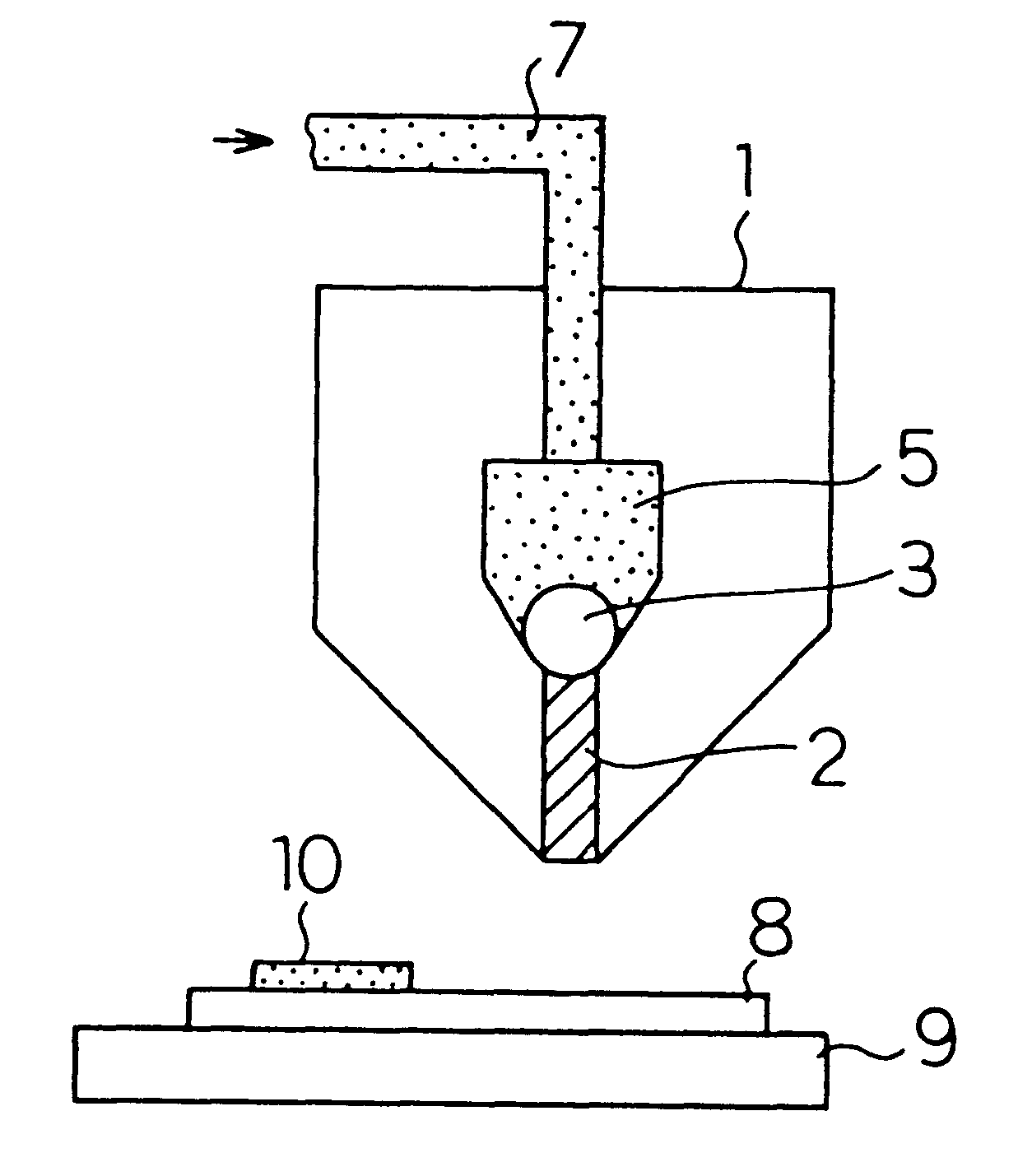
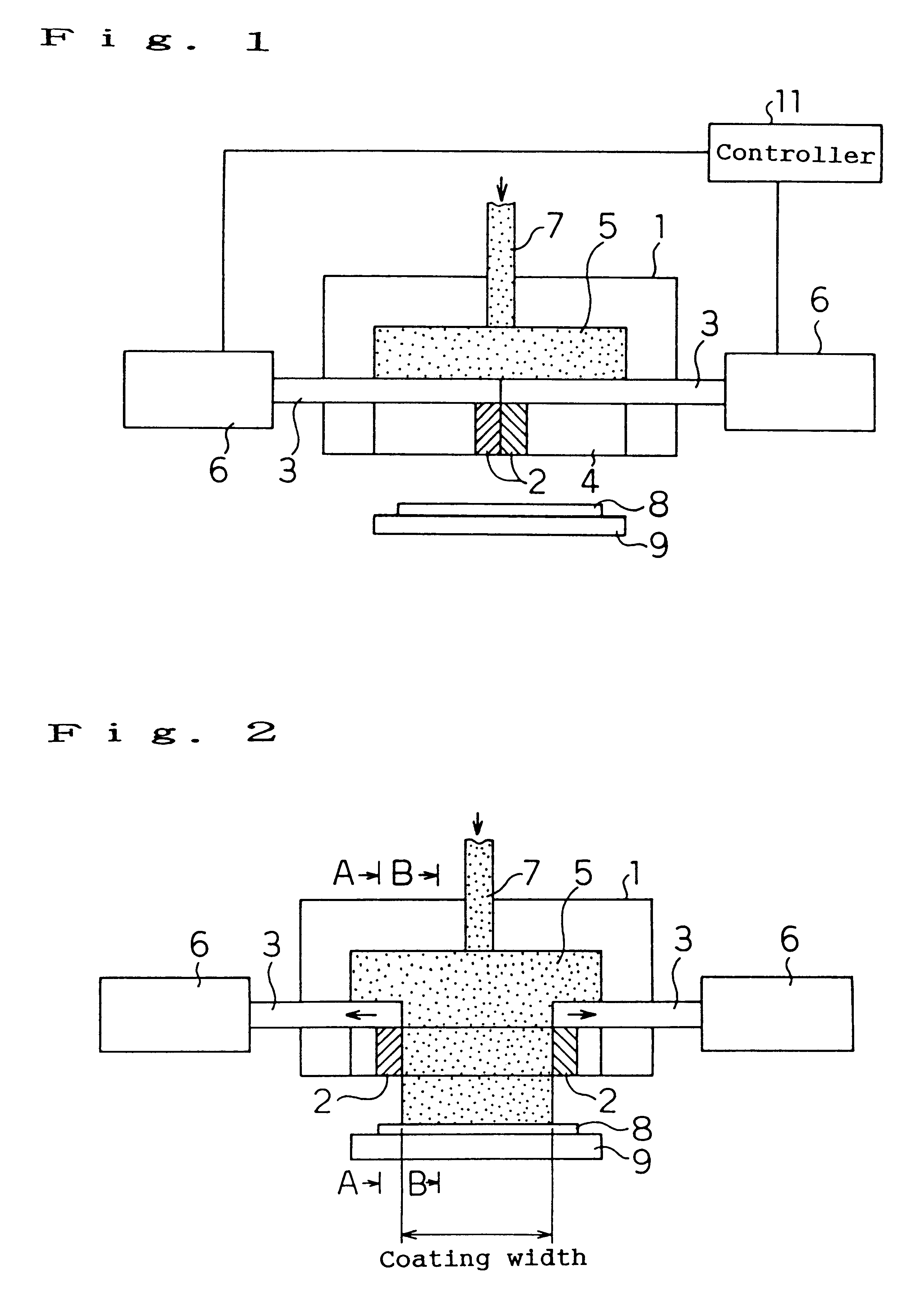
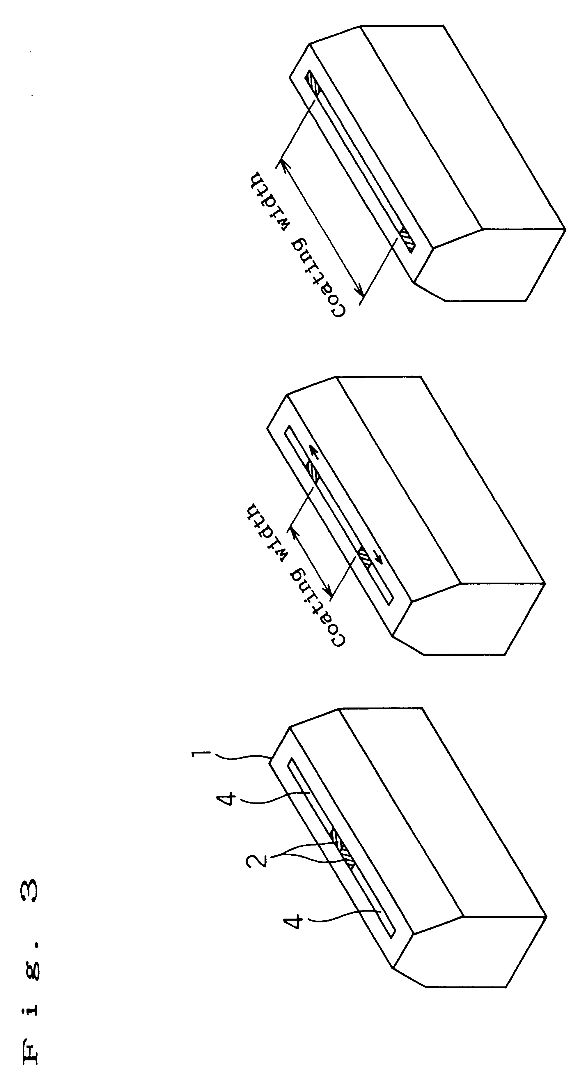
FIGS. 1 to 6 show schematic views of an apparatus for executing a coating method of the first embodiment of the present invention.
The structure of an apparatus for executing a coating method of the first embodiment of the present invention is described below. A nozzle 1 is provided with a pair of right and left blocking plates 2 with a thickness slightly smaller than the gap of a slit 4 and the blocking plates 2 are secured to a bar 3. An end of the bar 3 is provided with a moving unit 6 for moving the bar 3 in a coating width direction. Though the moving unit 6 is not restricted, it can use any mechanism such as a mechanism constituted by combining a servo motor, gear, and belt as long as the mechanism can change coating widths by moving the bar 3 and the blocking plates 2 by a controller 11 in accordance with a program stored in the controller 11.
A coating method of the first embodiment of the present invention is described below together with operations of the above apparatus. A ...
embodiment 2
FIGS. 1 to 6 and FIG. 12 show schematic views of the coating apparatus of the second embodiment of the present invention.
The structure of the coating apparatus of the second embodiment of the present invention is described below. A pair of right and left blocking plates 2 are used which is slightly thinner than the gap of the slit 4, the blocking plates 2 are secured to the bar 3, and the bar 3 connects with the moving unit 6 for moving the bar 3 in a coating width direction. The moving unit 6 can use any mechanism constituted by combining a servo motor, gear, and belt as long as the mechanism can change coating widths in accordance with a program stored in the controller 11. It is possible to change the moving distances of the bar 3 during coating in accordance with the program stored in the controller 11. The nozzle 1, as shown in FIG. 12, comprises two body blocks 20, a pair of right and left side blocks 21, and the blocking plates 2 secured by a pair of right and left bars 3. A ...
embodiment 3
FIGS. 13 to 18 show schematic views of the coating apparatus of the third embodiment of the present invention.
The structure of the coating apparatus of the third embodiment of the present invention is described below. A blocking plate 24 connects with a moving unit 6 for moving the blocking plate 24 in a coating width direction. The blocking plate 24 can be also connected to the moving unit 6 through a bar as shown in FIG. 18. The moving unit 6 is not restricted. The unit 6 can use any mechanism such as a mechanism constituted by combining a servomotor, gear, and belt as long as the mechanism can change coating widths in accordance with a program stored in a controller 11. It is possible to change the moving distances of the blocking plate 24 during coating in accordance with the program stored in the controller 11. Moreover, a nozzle 1 comprises two body blocks 20, a pair of right and left side blocks 21, and the blocking plate 24 secured to a pair of right and left bars as shown i...
PUM
 Abstract
Description
Claims
Application Information