Electronic ballast with feed-forward control

a technology of electronic ballast and control, applied in the direction of electric variable regulation, process and machine control, instruments, etc., can solve the problems of increasing power loss and negative impact of circuit performance of filtering components, and achieve the effect of increasing cost or adversely affecting performan

Inactive Publication Date: 2002-07-23
PHILIPS ELECTRONICS NORTH AMERICA
View PDF14 Cites 20 Cited by
  • Summary
  • Abstract
  • Description
  • Claims
  • Application Information

AI Technical Summary

Benefits of technology

to provide an electronic ballast for discharge lamps which can be made compact without substantially increasing cost or adversely affecting performance.
Such a ballast does not require a regulated DC power supply and will operate effectively with a filter capacitor that is much reduced in size from capacitors that are typically used to reduce ripple of the rectified DC power.

Problems solved by technology

If the operating frequency of ballast circuitry is increased sufficiently to achieve a substantial reduction in the sizes of magnetic and filtering elements, power losses tend to increase.
Decreasing the size of filtering components tends to have a negative impact on circuit performance.

Method used


Image

  • Electronic ballast with feed-forward control
  • Electronic ballast with feed-forward control
  • Electronic ballast with feed-forward control

Examples


Embodiment Construction

)

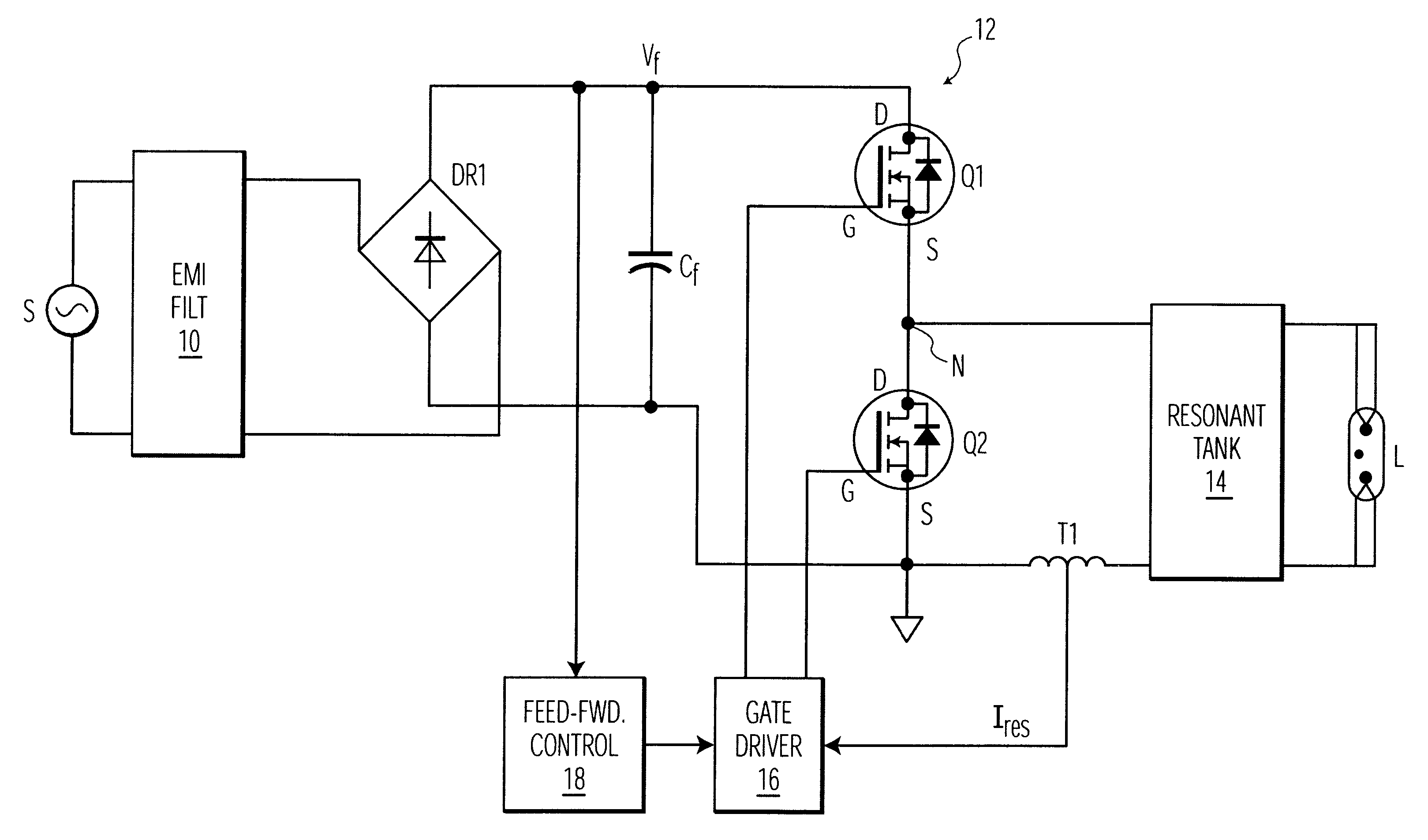
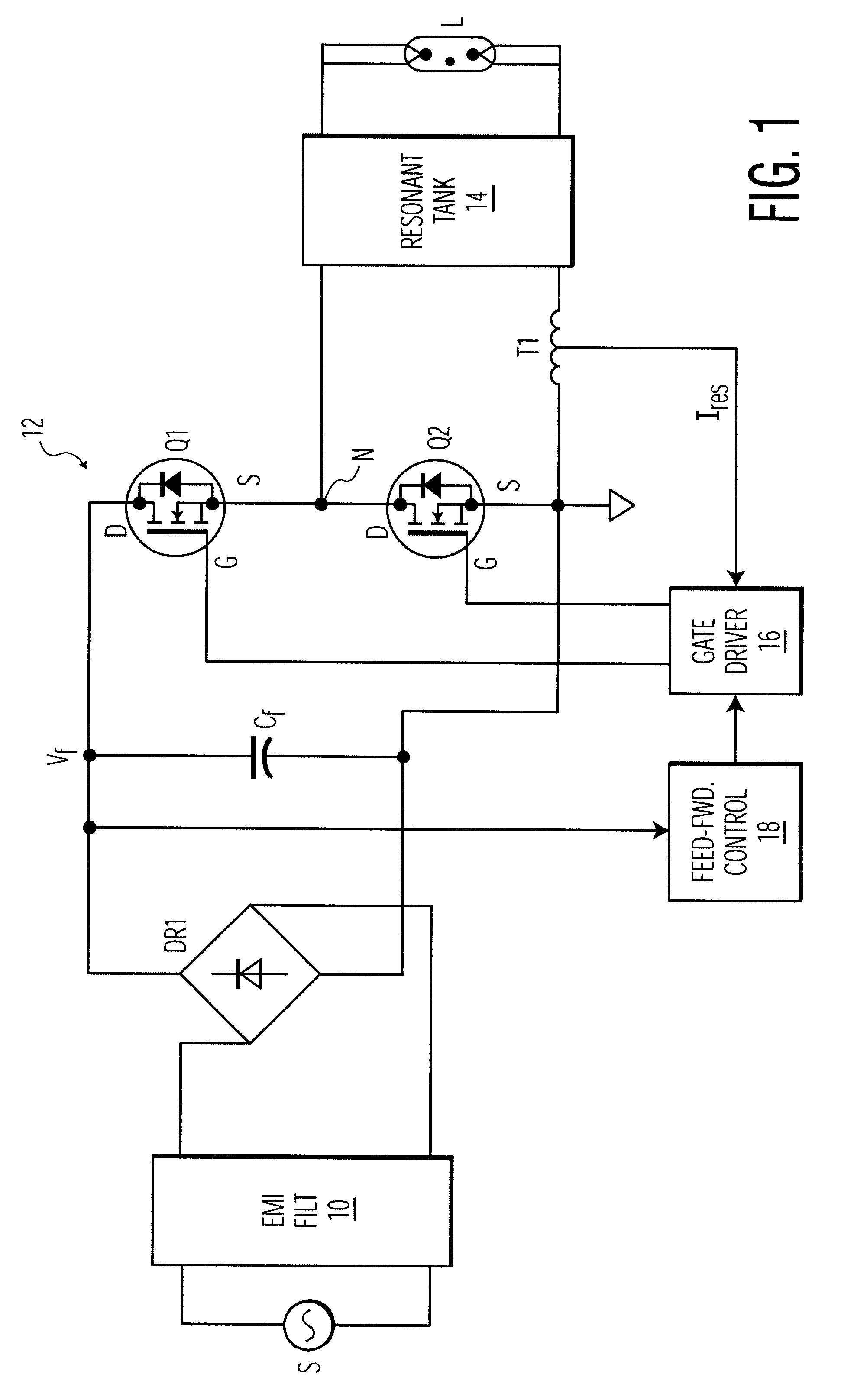
The exemplary system shown in FIG. 1 includes a source of AC power S, a discharge lamp L (e.g. a fluorescent lamp) and a ballast for controllably passing power to the lamp from the source S. The ballast includes an EMI filter 10, a bridge rectifier DR1, a line-filter capacitor C.sub.f, a half-bridge converter 12, a resonant tank 14 (e.g. a multi-layered piezoelectric transformer), a current transformer T1, a gate driver circuit 16 and a feed-forward control circuit 18.

The EMI filter 10 serves to isolate the AC power source S from interference signals generated within the ballast (e.g. high-frequency switching signals generated by the converter 12).

The bridge rectifier DR1 and the filter capacitor C.sub.f convert the AC power from the source S to rectified, but unregulated, DC power having a varying DC voltage V.sub.f. Together, this rectifier and capacitor form a DC power source that is conventional except for its simplicity and the relatively small size of the filter capacitor tha...


PUM


Abstract

An electronic ballast which is capable of compactly powering a discharge lamp from a source of rectified, but unregulated, power having a varying DC voltage. The ballast includes a selfoscillating converter powered by the DC voltage for producing pulses at a nominal operating frequency which is determined by a resonant tank. The resonant tank converts the pulses to a sinusoidal current for powering the discharge lamp and includes an inductive impedance.in series with the lamp for providing a voltage drop which varies with the operating frequency. A feed-forward control circuit is coupled to the converter for automatically varying the operating frequency directly with variations in the DC source voltage. The voltage drop across the inductive impedance is substantially proportional to the magnitude of the DC source voltage. This enables regulation of the voltage supplied to the discharge lamp by the ballast without sensing the lamp voltage itself.

Description

1. Field of the InventionThis invention relates to electronic ballasts for discharge lamps such as fluorescent lamps and, in particular, to such ballasts which are useful in applications where compact size is desirable.2. Description of Related ArtThere is an ever-increasing demand for smaller electronic ballasts. In order to achieve this goal, a variety of problems must be overcome, for example:If the operating frequency of ballast circuitry is increased sufficiently to achieve a substantial reduction in the sizes of magnetic and filtering elements, power losses tend to increase.Decreasing the size of filtering components tends to have a negative impact on circuit performance.It is an object of the invention to provide an electronic ballast for discharge lamps which can be made compact without substantially increasing cost or adversely affecting performance.In accordance with the invention, an electronic ballast includes a source of power having a varying DC voltage, a self-oscilla...

Claims


Application Information

Patent Timeline
Patent Type & Authority Patents(United States)
IPC IPC(8): H02M7/538H05B41/282H05B41/28H05B41/39H05B41/392H05B41/24
CPCH02M7/53803H05B41/2827H05B41/392H02M2001/0022Y02B20/185Y02B70/1441H02M1/0022Y02B20/00Y02B70/10
Inventor SABATE, JUAN A.
Owner PHILIPS ELECTRONICS NORTH AMERICA
Why Eureka
Try Eureka