
Electrical power cord manager for a lighting fixture

a technology for lighting fixtures and power cord managers, which is applied in the field of installation of electric lighting fixtures, can solve the problems of reducing the visibility of power cords, affecting the use of lighting fixtures, and the rigid stem design became impractical, and achieves uniform cross-sectional shap

Inactive Publication Date: 2002-08-06
ABL IP HLDG
View PDF13 Cites 12 Cited by
  • Summary
  • Abstract
  • Description
  • Claims
  • Application Information

AI Technical Summary

Benefits of technology

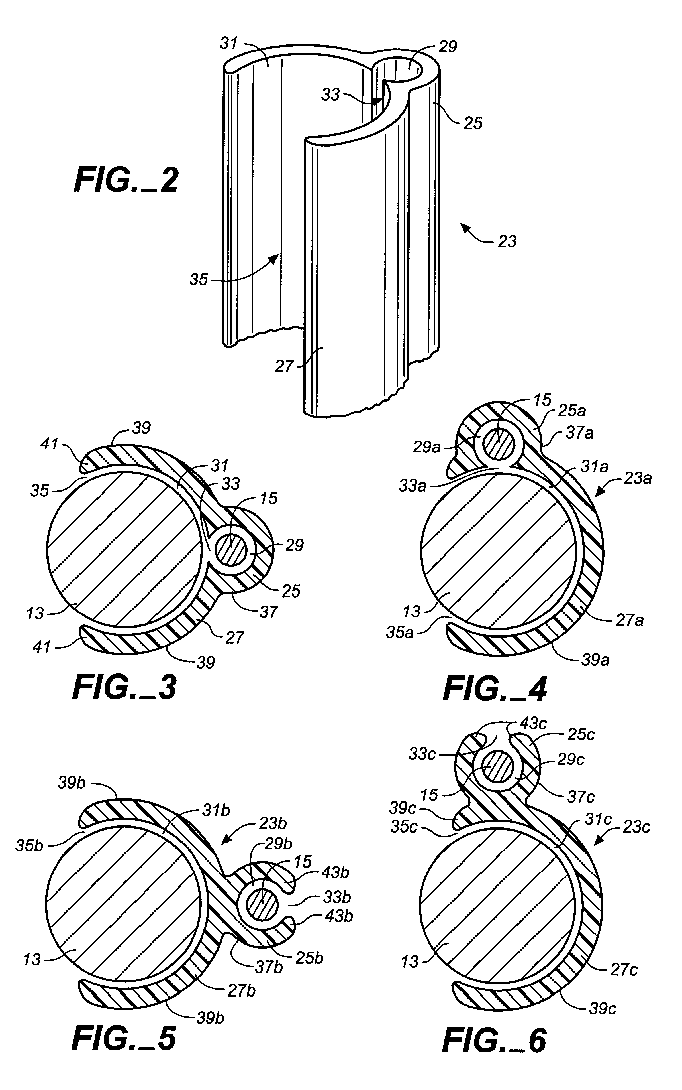
Briefly, the present invention is a power cord manager for the power cord of a suspended electric lighting fixture having a suspension cable near the location of the power cord. The power cord manager is comprised of first and second elongated body portions which are preferably integrally connected and which preferably have a uniform cross-sectional shape such that the cord manager can be fabricated from an extruded strip of material, such as plastic or aluminum, cut to a desired length.

Problems solved by technology

However, rigid stem designs became impractical with the introduction of earthquake building codes in earthquake-prone areas, such as California, which require that a fixture be allowed to sway during a seismic event.
But ball stems have a decided disadvantage in that they, like rigid stems, are relatively costly and difficult to install.
The problem with aircraft cable is the visibility of the power cords dropped next to the cable.
Power cords have natural bends which, unlike the finished appearance of stem systems, present a casual or awkward appearance which can be visually objectionable.
To mitigate this problem, designers often require that the power cord be tied to the suspension cable using cable ties or clips, however, in many cases this still does not provide the finished look desired.
First, with ties or clips it is difficult to keep the cord perfectly straight against the suspension cable, and the ties and clips themselves can be a visual detraction.

Method used


Image

  • Electrical power cord manager for a lighting fixture
  • Electrical power cord manager for a lighting fixture
  • Electrical power cord manager for a lighting fixture

Examples


Embodiment Construction

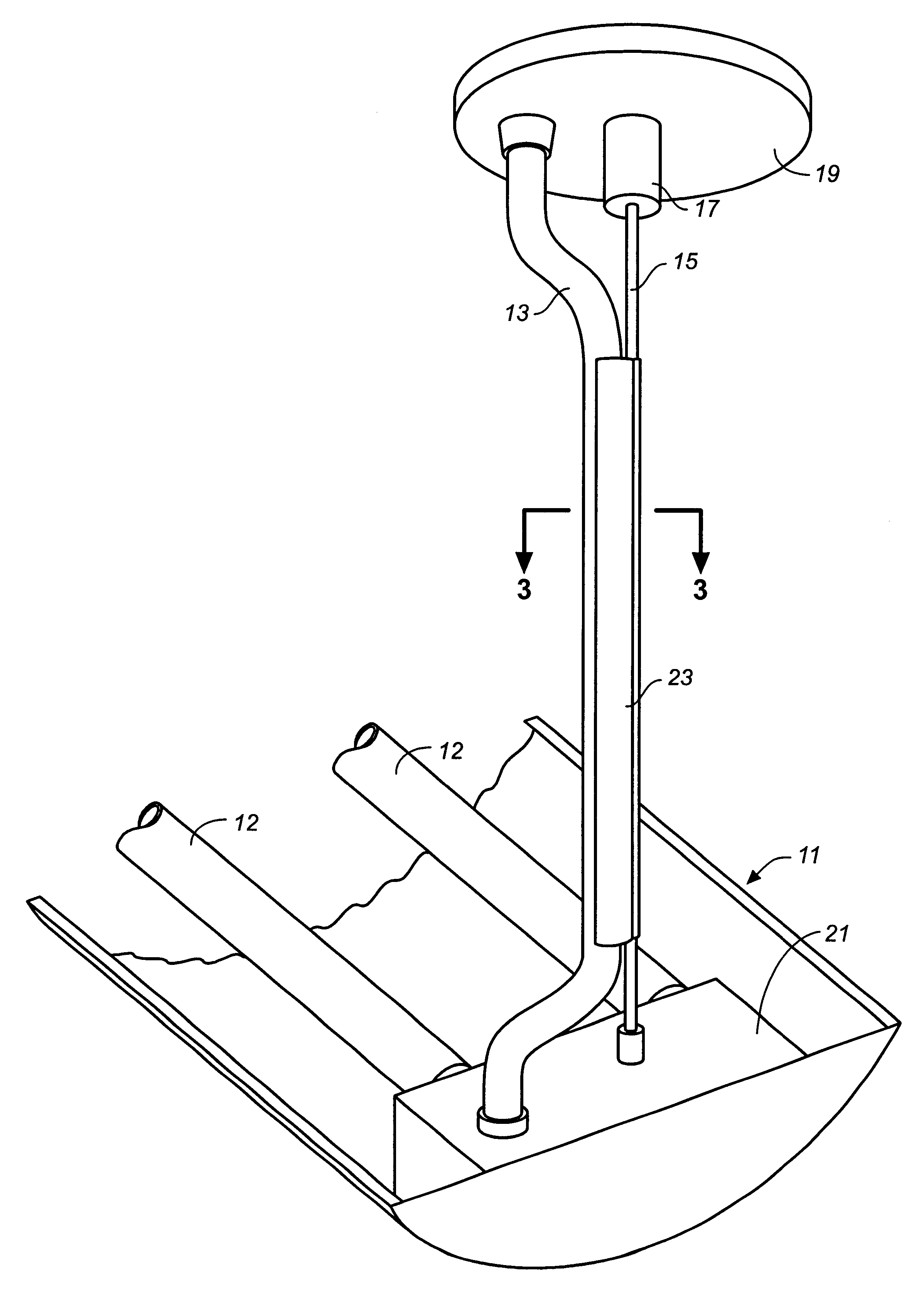
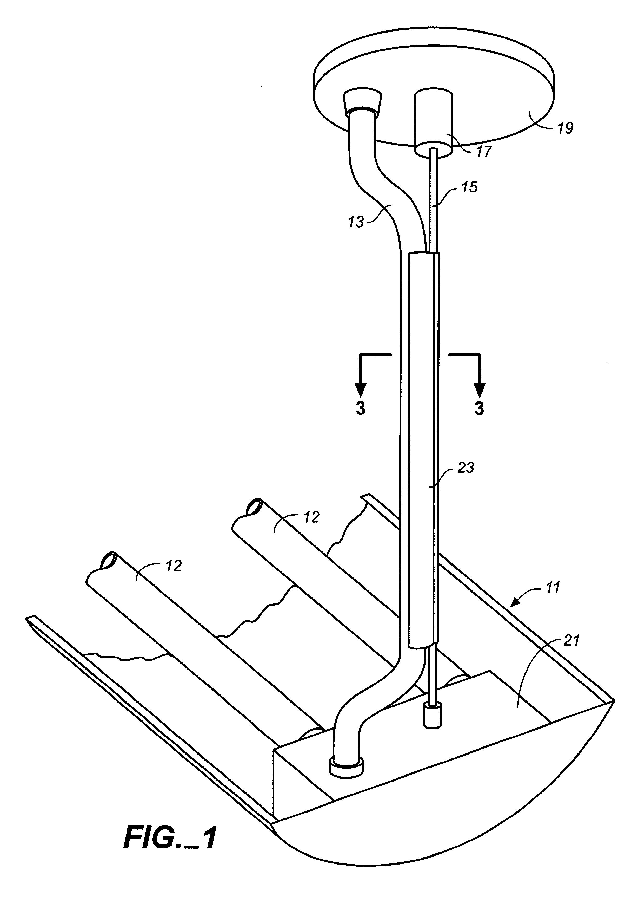
Turning now to the drawings, FIG. 1 shows a fluorescent lighting fixture 11 with fluorescent lamps 12 and a flexible electrical power cord 13 suspended by means of a suspension cable 15 at an electrical feed location of an overhead ceiling, such as a grid ceiling (not shown). The suspension cable is typically provided in the form of flexible steel aircraft cable having an internally threaded fitting 17 for attaching the top end of the cable to a threaded hanger rod (not shown) which extends through ceiling canopy 19 from an overhead load bearing ceiling hanger bracket such as disclosed in U.S. Pat. No. 5,484,076. The bottom end of the cable is in turn attached to a mounting bracket 21 at end of the fixture, The electrical power cord 13, which is also connected to the fixture through mounting bracket 21, has sufficient length to be flexibly routed along the suspension cable.

The power cord 13 and suspension cable 15 are tied together in a finished, aesthetically pleasing installation ...


PUM


Abstract

A cord manager for a suspended electric lighting fixture holds the fixture's power cord in close parallel relation to the fixture's suspension cable at electrical feed locations. The cord manager, which is suitably fabricated of extruded plastic, has an elongated first body portion with a lengthwise cable retention channel and an elongated second body portion having a power cord retention channel. In one embodiment of the invention, the retention channel for the suspension cable opens onto the power cord retention channel. In another embodiment, the suspension cable and power cord retention channels open outwardly away from each other. The cord manager provides the clean, finished look to the lighting installation at power feed locations.

Description

BACKGROUND OF INVENTIONThe present invention generally relates to the installation of electric lighting fixtures, and more particularly to visual distractions associated with the installation of ceiling suspended lighting fixtures having exposed electrical power cords that must be extended between the fixtures and the overhead ceiling.Lighting designs for architectural spaces frequently include linear fluorescent lighting fixtures suspended from an overhead ceiling structure where the lighting fixtures become an architectural element within the space. In office environments a typical lighting installation will include the suspension of runs of linear direct or indirect lighting fixtures below a grid ceiling from multiple suspension points located on the ceiling grid. Each run of fixtures will require at least one power feed location where a potentially unsightly power cord must be run from the lighting fixture up to an electrical junction box above the ceiling grid. In older install...

Claims


Application Information

Patent Timeline
Patent Type & Authority Patents(United States)
IPC IPC(8): F21V27/00F21S8/04F21S8/06F21V21/10F21V21/104
CPCF21S8/06F21V27/00F21V21/104Y10T24/3931F21Y2103/00F21V23/002F21Y2113/00
Inventor HERST, DOUGLAS J.SALMAN, UTKAN
Owner ABL IP HLDG
Learn More