Self-charge mouse
A self-charging, mouse technology, applied in the direction of collectors, electric vehicles, electrical components, etc., can solve the problems of high cost, inconvenience, environmental pollution, etc., and achieve the effect of saving resources, reducing use costs, and improving safety.
- Summary
- Abstract
- Description
- Claims
- Application Information
AI Technical Summary
Problems solved by technology
Method used
Image
Examples
Embodiment 1
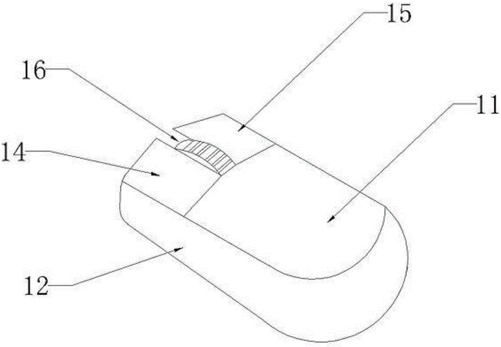
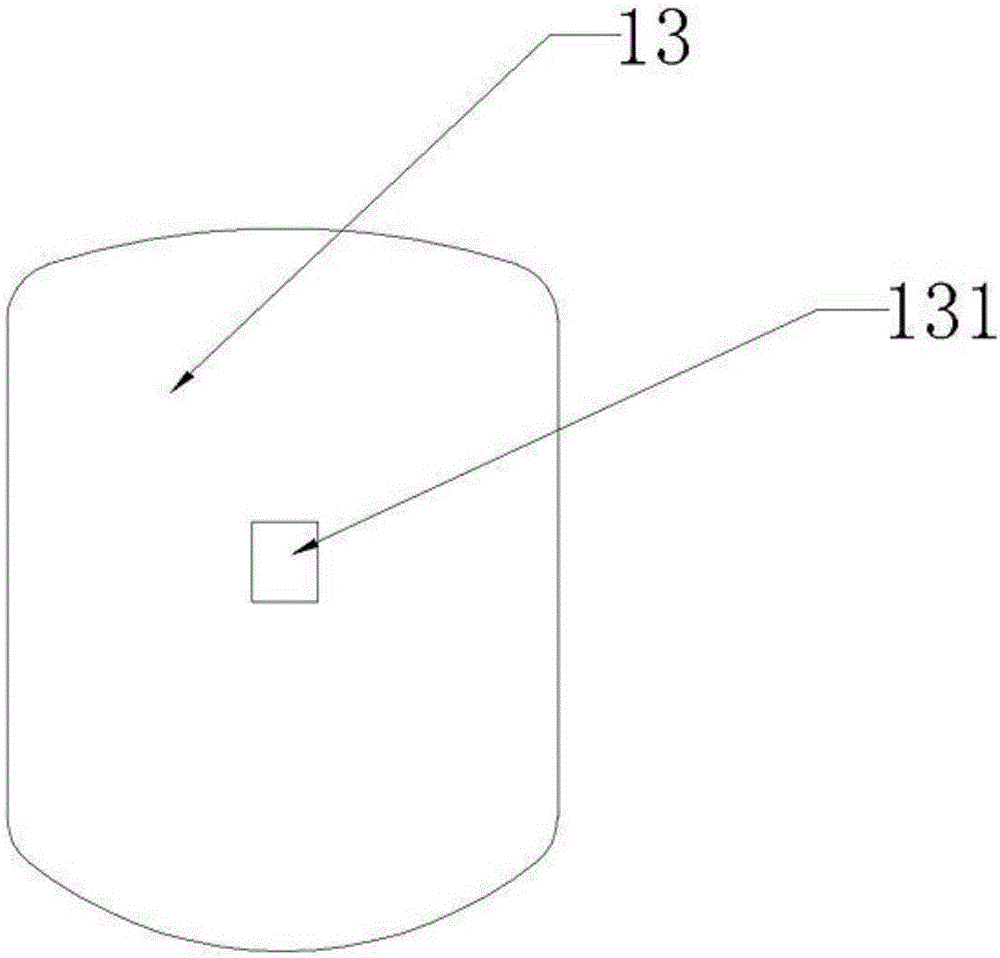
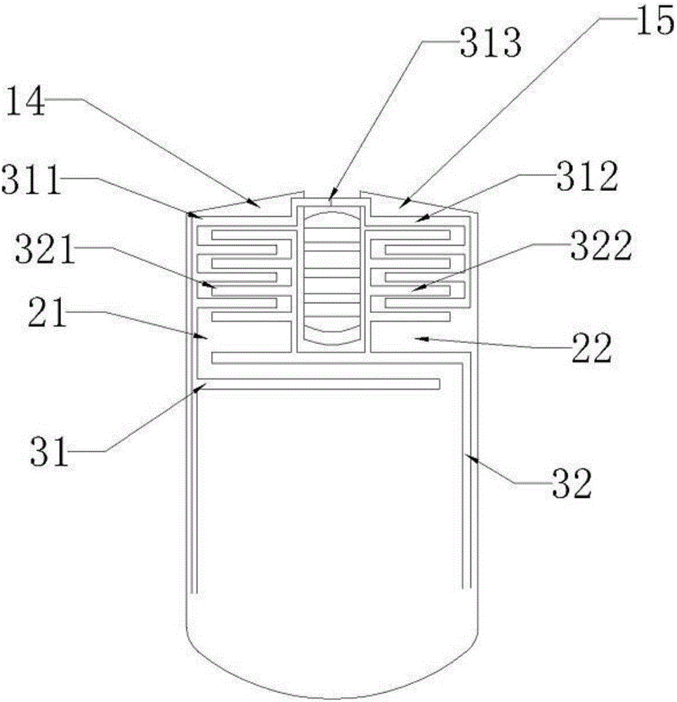
[0043] See attached image 3 - attached Figure 6 , the energy conversion module includes an electrical inlay layer, the electrical inlay layer is arranged under the left keypad 14 and the right keypad 15, the electrical inlay layer is made of piezoelectric material, when pressed When an electrical material is deformed by an external force in a certain direction, it will produce a piezoelectric effect, and a polarization phenomenon will occur inside it, and at the same time, positive and negative charges will appear on its two opposite surfaces. Therefore, when the key board is pressed, the pressure can be transmitted to the electrical inlay layer, the electrical inlay layer is deformed by the pressure, and the electrical inlay layer produces a piezoelectric effect. The energy collection module includes a first electrode 31, a second electrode 32, a rectifying device and a rechargeable battery, the first electrode 31 and the second electrode 32 are connected to the rectifying...
Embodiment 2
[0047] The difference from Example 1 is that see the attached Figure 7 And attached Figure 8 , the energy conversion module includes a follow-up production section 41, a resonant fixed section 51, a resonant production section 52 and a resonant counterweight section 53, the energy conversion module is arranged inside the housing of the self-charging mouse, the The follow-up production section 41, the resonant fixed section 51, the resonant production section 52 and the resonant counterweight section 53 are sequentially arranged behind the roller 16, and the two sides of the resonant fixed section 51 are symmetrically provided with clip joints. Slot 511, the snap-in slot 511 is provided with a snap-in device 512, and a snap-in hole is provided at a corresponding position of the housing of the self-charging mouse for fixing the snap-in device 512, namely The engaging device 512 is always stationary relative to the casing, so the energy conversion module can slide back and for...
Embodiment 3
[0055] The difference from Example 1 is that see the attached Figure 9 And attached Figure 10 , the energy conversion module includes a magnetic layer 6, an actuator 7, and a self-collecting cavity 8, and the self-collecting cavity 8 includes a first self-collecting cavity 81, a second self-collecting cavity 82, and a third self-collecting cavity 83, the The self-collection cavity 8 is arranged inside the housing, and the magnetic layer 6 is arranged on the upper part of the self-collection cavity 8, so that the self-collection cavity 8 is filled with magnetic lines of different intensities, and the actuator 7 It is a conductor, preferably metal, more preferably a metal ball or a dumbbell-shaped metal rod, both of which are solid structures. The actuator 7 slides at a non-uniform speed inside the self-collecting chamber 8 , and electromagnetic induction occurs when the cutting magnetic field lines move continuously, and an induced electromotive force is formed on the surfac...
PUM
 Abstract
Description
Claims
Application Information
 - R&D
- Intellectual Property
- Life Sciences
- Materials
- Tech Scout
- Unparalleled Data Quality
- Higher Quality Content
- 60% Fewer Hallucinations
Browse by: Latest US Patents, China's latest patents, Technical Efficacy Thesaurus, Application Domain, Technology Topic, Popular Technical Reports.
© 2025 PatSnap. All rights reserved.Legal|Privacy policy|Modern Slavery Act Transparency Statement|Sitemap|About US| Contact US: help@patsnap.com


