Supercharge Your Innovation With Domain-Expert AI Agents!

Mechanical loading of a land grid array component using a wave spring

Inactive Publication Date: 2002-08-06
HEWLETT PACKARD DEV CO LP
View PDF7 Cites 12 Cited by
  • Summary
  • Abstract
  • Description
  • Claims
  • Application Information

AI Technical Summary

Problems solved by technology

However, achieving such large perpendicular forces with conventional springs requires either the use of long springs (and screws) that vertically project above the substrate, or the use of shorter springs with very large spring constants.
One problem with using long springs (and screws) is that the vertical projection above the plane of the substrate seriously limits the packaging density of adjacent parallel substrates in order to avoid contact to an adjacent substrate by the springs and screws of another substrate.
A problem with using shorter springs with very large spring constants is that the clamping force is determined by the mechanical tolerances in compressing the springs, but there is a significant manufacturing deviation (e.g., + / -10% in the spring constant from one spring to another spring in the same manufactured lot.
Therefore, if two springs with very large spring constants are mechanically compressed by an equal distance, the resulting forces applied by the two springs can be greatly unequal, causing uneven clamping and uneven electrical contacts to the interposer and the conductive pads of the substrate under the LGA component.
Uneven electrical contacts in turn can cause poor electrical contacts that produce a permanent or an intermittent failure in system operation.
Another problem with short, conventional springs is that the springs are compressed near or to a coil-bound or solid height condition outside of their usable range.
Without improved springs to apply the clamping force, very long springs will be needed, or short springs with high spring constants and large force variations will produce an increasing number of poor electrical contacts between LGA components, interposers, and substrates, resulting in increasing operational and reliability failures.

Method used


Image

  • Mechanical loading of a land grid array component using a wave spring
  • Mechanical loading of a land grid array component using a wave spring
  • Mechanical loading of a land grid array component using a wave spring

Examples


Embodiment Construction

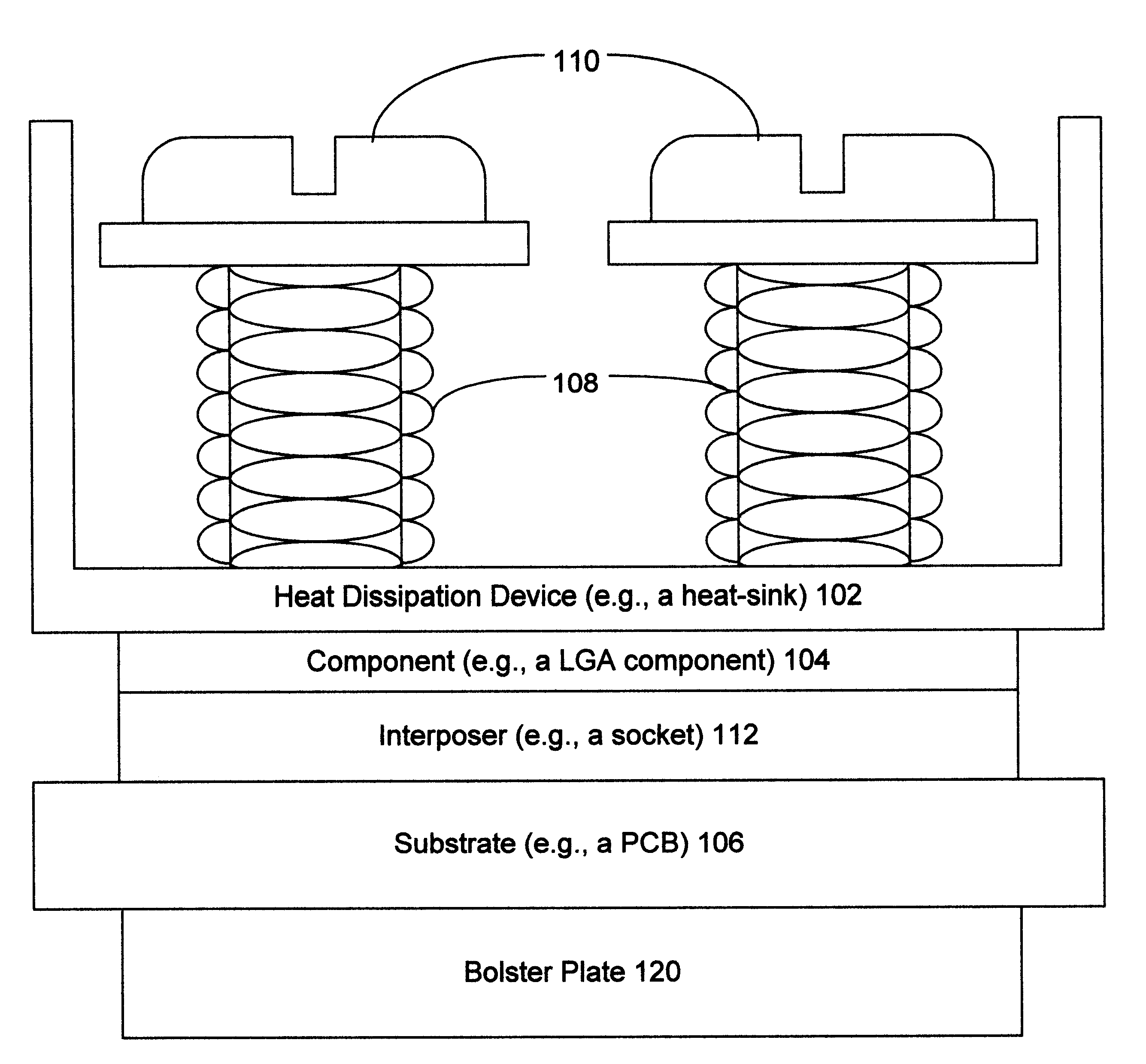
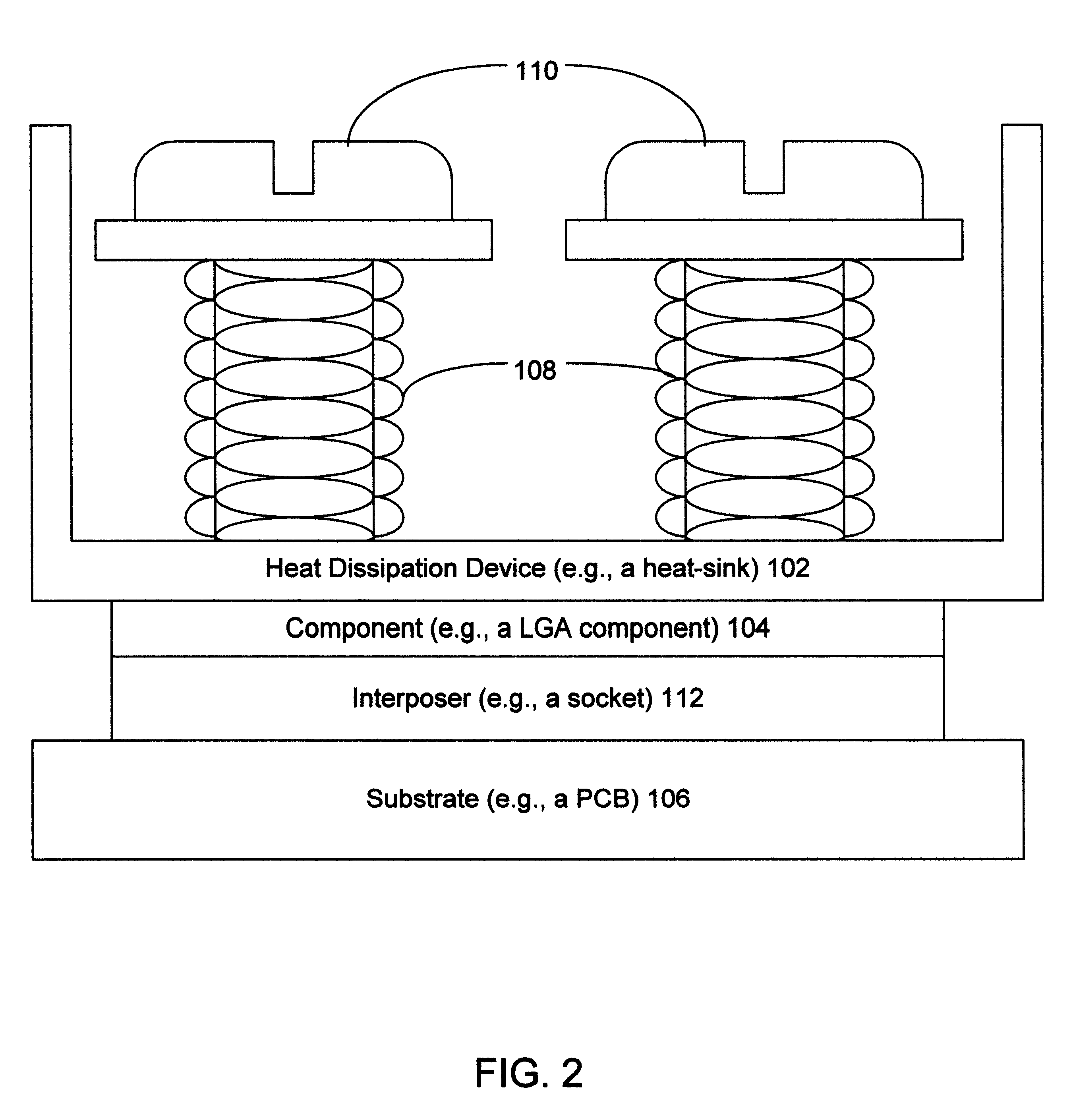
The present invention uses a wave spring to clamp a component to a substrate, such as a printed circuit board (PCB) or a multi-chip module. While the discussion below is directed to an application of the invention to a LGA component and a heat-sink assembled on a substrate (e.g., a PCB), the invention can also be applied to other types of electrical components (e.g., transformers, power supplies, connectors) held to a substrate by using another structure, for example a block, a clamp, or a heat dissipation device (e.g., a heat-sink, a heat-pipe, a fluid cooling device, a cooling fan, or an equivalent). Components can be also assembled on other substrates (e.g., multi-chip modules, and flexible substrates upon which electrical components can be assembled).

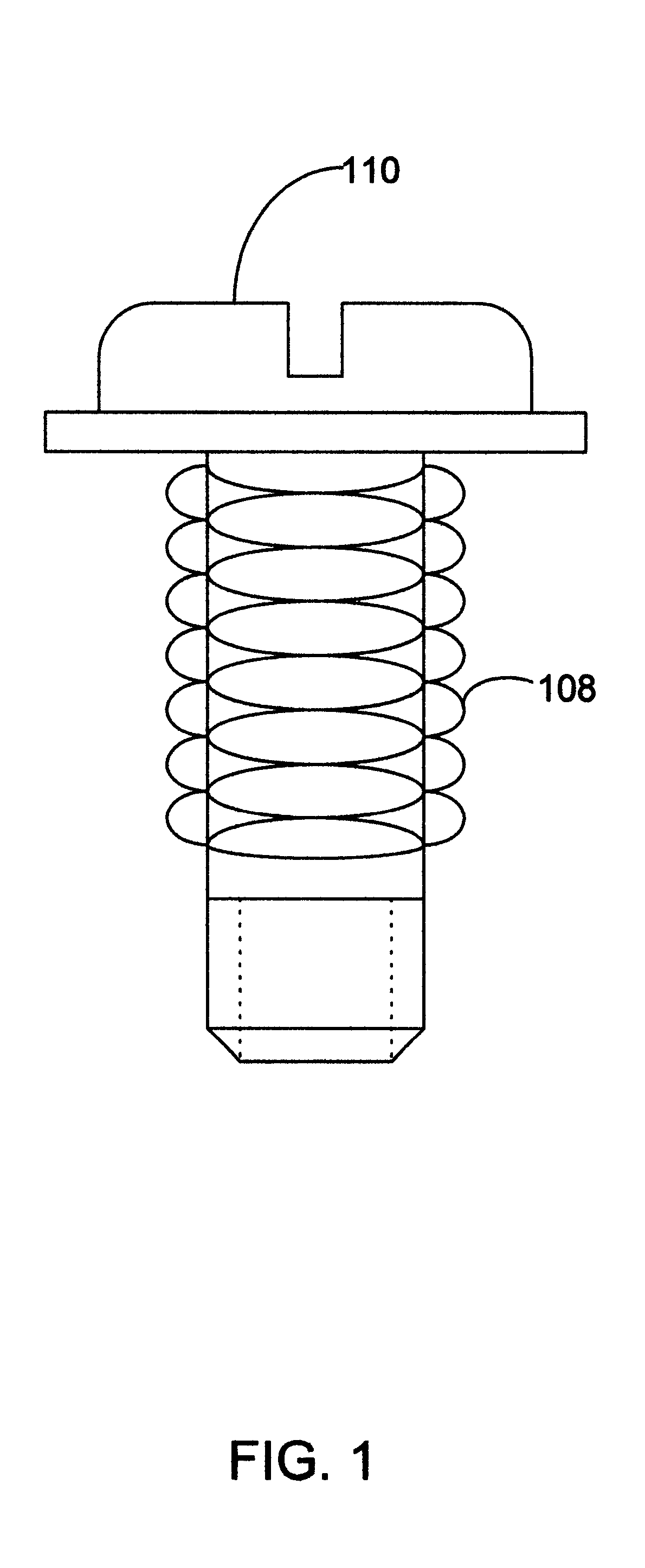
FIG. 1 illustrates a side view of a wave spring 108 on a bolt 110, according to one embodiment of the present invention. The wave spring 108 (e.g., a Spirawave.RTM. spring such as a Crest-to-Crest.RTM. spring available from Smalley....


PUM

PropertyMeasurementUnit
Flexibilityaaaaaaaaaa
Areaaaaaaaaaaa

Abstract

A method and substrate using a wave spring to clamp a component to the substrate. One embodiment of the invention involves a method to use a wave spring to clamp a component to a substrate. The method includes placing the component on the substrate, placing a structure having holes on the component, placing a number of wave springs on a corresponding number of bolts, inserting the bolts into the holes in the structure, and attaching the bolts to the substrate. A second embodiment of the invention involves a substrate with an electrical contact area, an interposer placed on the electrical contact area, a component placed on the interposer, a block having holes placed on the component, bolts and wave springs inserted in the holes, wherein the bolts and wave springs clamp the component, the interposer and the substrate together on the electrical contact area of the substrate.

Description

1. Field of the InventionThis invention relates generally to using a wave spring to clamp an IC component to a substrate, and more specifically relates to using a wave spring to clamp a land grid array (LGA) IC component to a printed circuit board.2. Description of the Prior ArtIn many data processing systems (e.g., computer systems, programmable electronic systems, telecommunication switching systems, control systems, and so forth) very large pin count electrical components (e.g., application specific integrated circuits and processor chips) are assembled on substrates (e.g., printed circuit boards, other flexible substrates, multi-chip modules, and equivalents). One type of packaging that is frequently used for a very large pin count electrical component is what is commonly known as a land grid array (LGA) component. Electrical connections between the LGA component pins and the corresponding conductive pads on the substrate are typically achieved by compressing an interposer (e.g....

Claims


Application Information

Patent Timeline
IPC IPC(8): H01L23/34H01L23/40
CPCH01L23/40H01L23/4006H01L2023/405Y10T29/4913H01L2924/0002H01L2023/4081H01L2924/00
Inventor HENSLEY, JAMES DAVIDCROMWELL, STEPHEN DANIELMEYER, GREGORY S.
Owner HEWLETT PACKARD DEV CO LP
Features
  • R&D
  • Intellectual Property
  • Life Sciences
  • Materials
  • Tech Scout
  • Unparalleled Data Quality
  • Higher Quality Content
  • 60% Fewer Hallucinations
Learn More