
Apparatus for the in-process dimensional checking of cylindrical parts

Inactive Publication Date: 2002-08-13
MARPOSS SPA
View PDF21 Cites 55 Cited by
  • Summary
  • Abstract
  • Description
  • Claims
  • Application Information

AI Technical Summary

Problems solved by technology

However, in some cases there can be problems owing to the limited space available on the machine tool for mounting the checking apparatus including the guide elements that have surfaces with appropriate extension for guaranteeing the correct cooperation with the crankpin to be checked.

Method used


Image

  • Apparatus for the in-process dimensional checking of cylindrical parts
  • Apparatus for the in-process dimensional checking of cylindrical parts
  • Apparatus for the in-process dimensional checking of cylindrical parts

Examples


Embodiment Construction

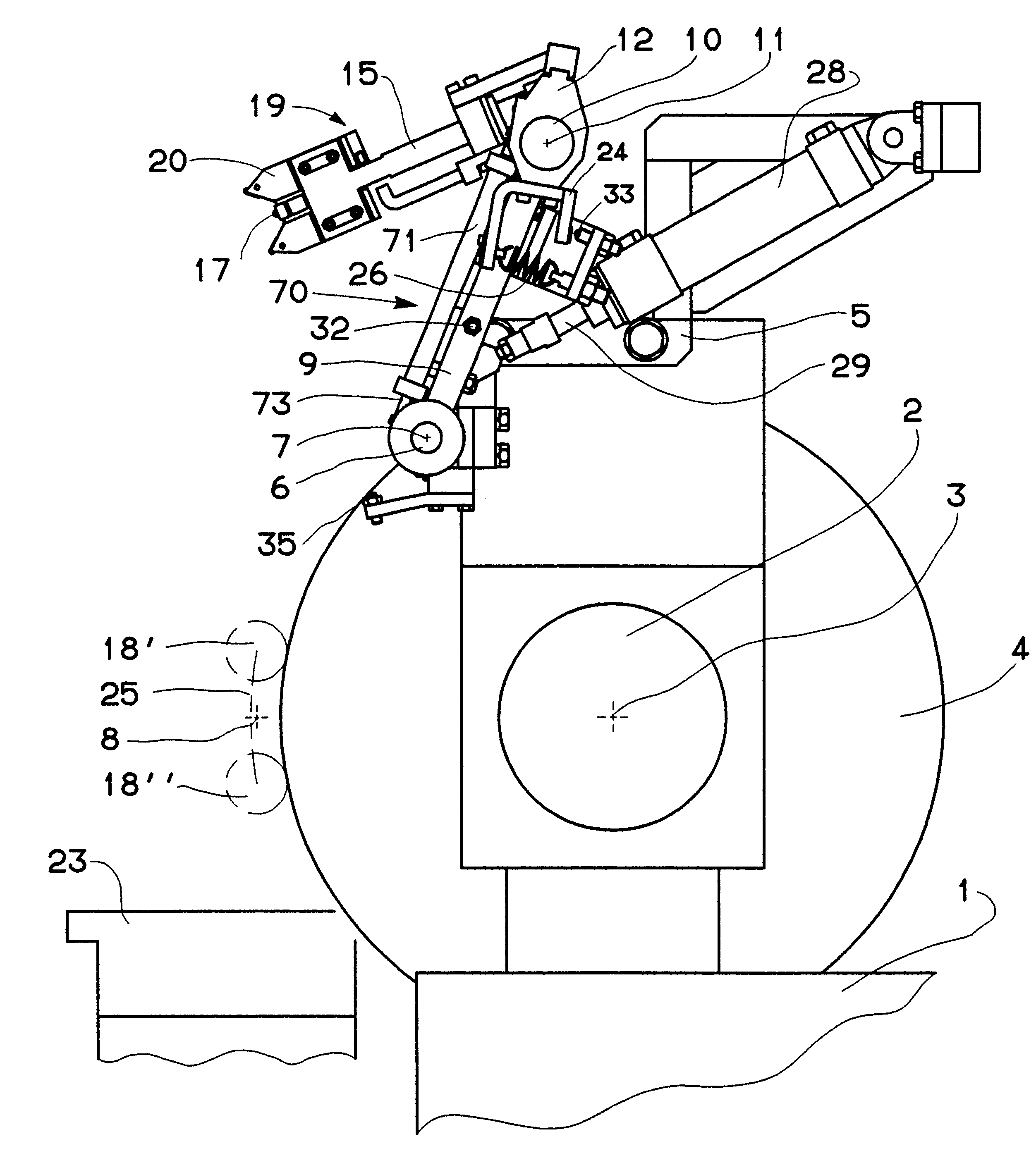
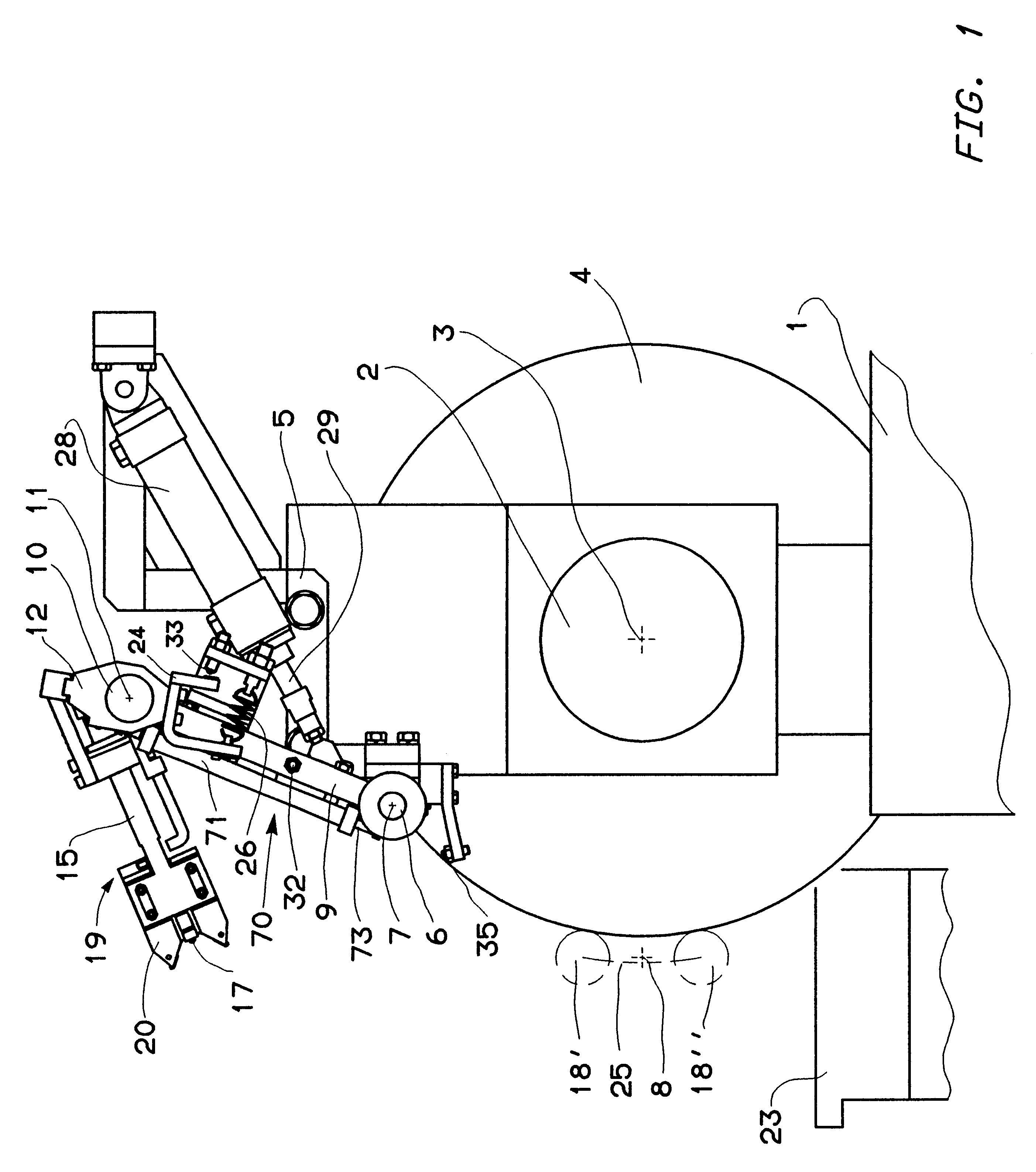
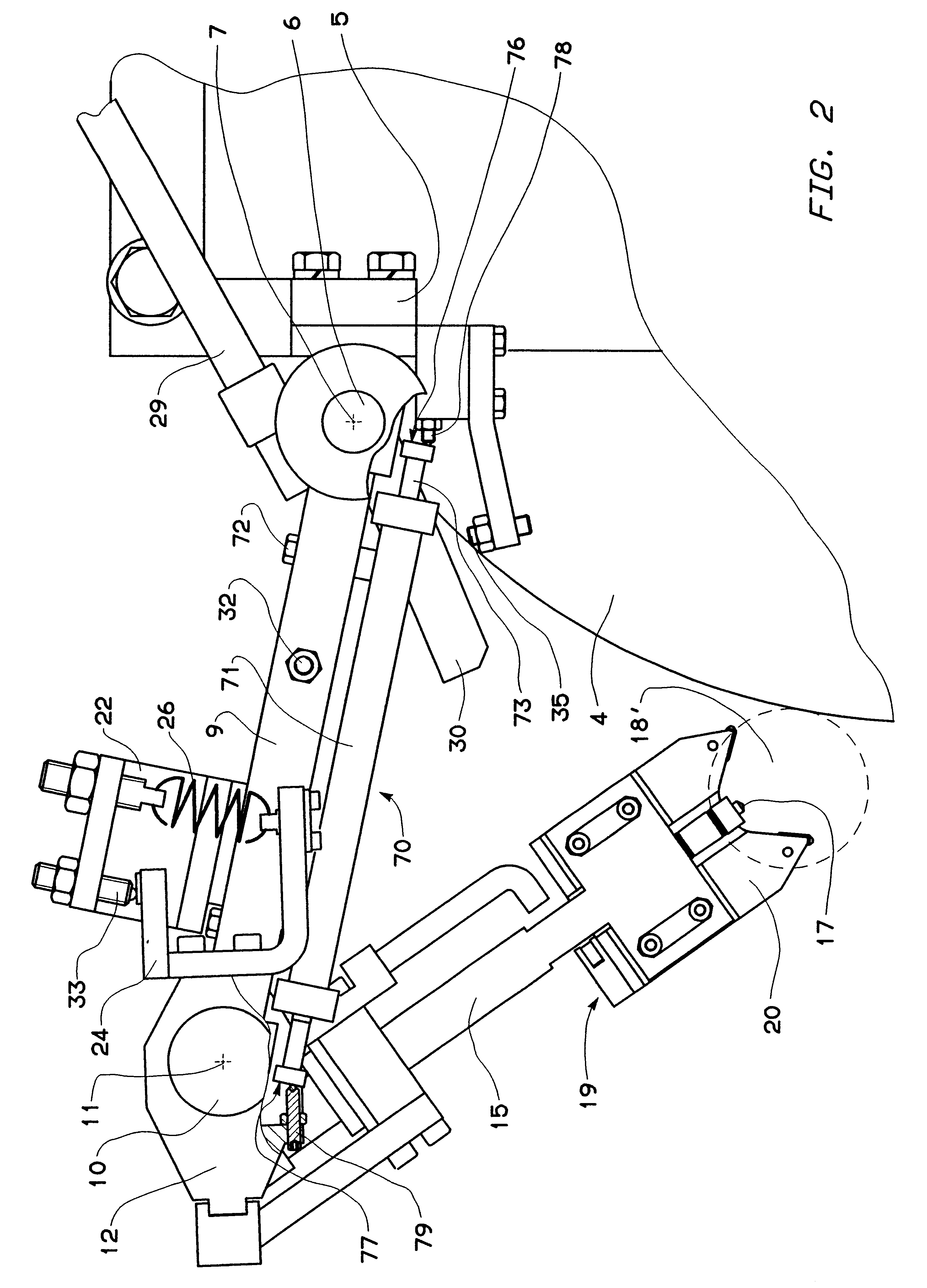
With reference to FIGS. 1 to 5, the grinding-wheel slide 1 of a computer numerical control ("CNC") grinding machine for grinding crankshafts supports a spindle 2 that defines the axis of rotation 3 of grinding wheel 4. The grinding-wheel slide 1 carries a support device including a support element 5 that, by means of a rotation pin 6, with preloaded bearings--not shown--, supports a first rotating, coupling element 9. Pin 6 defines a first axis of rotation 7 parallel to the axis of rotation 3 of grinding wheel 4 and to the axis of rotation 8 of the crankshaft. In turn, coupling element 9, by means of a rotation pin 10, with preloaded bearings--not shown--, defining a second axis of rotation 11 parallel to the axes of rotation 3 and 8, supports a second rotating, coupling element 12.

At the free end of coupling element 12 there is coupled a guide casing 15 wherein there can axially translate a transmission rod 16 carrying a feeler 17 for contacting the surface of crankpin 18 to be che...


PUM


Abstract

An apparatus for checking the diameter of crankpins of a crankshaft in the course of the machining in a grinding machine includes a Vee-shaped reference device, a measuring device associated with the reference device and including a feeler axially movable along the bisecting line of the Vee-shaped reference device, and a support device with a first arm rotating with respect to a support arranged on the grinding-wheel slide and a second arm rotating with respect to the first and carrying the Vee-shaped reference device.A guiding mechanism includes a limiting device, with mutually abutting surfaces and coupled to the support device, that guides the displacement of the reference device along a trajectory substantially parallel to the profile of the grinding wheel, allows the engagement of the reference device on a crankpin to be checked while the latter is orbitally moving, and does not interfere with the displacements of the support device caused by the orbital motion of the crankpin in the checking condition.

Description

1. FIELD OF THE INVENTIONThe present invention relates to an apparatus for checking the diameter of a cylindrical part, rotating about a geometrical axis, e.g. an orbitally rotating crankpin, in the course of the machining in a numerical control grinding machine including a grinding-wheel slide, with a reference device for cooperating with the part to be checked, a measuring device movable with the reference device, a support device for supporting the reference device and the measuring device, the support device having a support element adapted to be fixed to the grinding-wheel slide, a first coupling element coupled to the support element so as to rotate about a first axis of rotation, and a second coupling element carrying the reference device and coupled to the first coupling element so as to rotate with respect to it about a second axis of rotation parallel to the first axis of rotation, a control device for controlling automatic displacements of the apparatus from a rest positi...

Claims


Application Information

Patent Timeline
Patent Type & Authority Patents(United States)
IPC IPC(8): B24B5/42B24B49/04B24B49/02B24B5/00G01B5/08B24B49/08B23Q17/20
CPCB24B5/42B24B49/04B24B49/045G01B5/08
Inventor DALL'AGLIO, CARLOMONTANARI, WILLIAM
Owner MARPOSS SPA
Learn More