Downhole optical sensor system with reference

a technology of optical sensor and reference, applied in the field of optical sensing systems, can solve the problems of inconvenient use, small size of optical sensors, and low cost, and achieve the effects of improving the accuracy of measurement results

Active Publication Date: 2005-04-28
OPTOPLAN
View PDF8 Cites 46 Cited by
  • Summary
  • Abstract
  • Description
  • Claims
  • Application Information

AI Technical Summary

Problems solved by technology

Additionally, optical sensors tend to be small, lightweight, and physically robust.
However, instabilities in the frequency of an interrogating light signal arriving at an optical sensor from a light source may cause variations in sensor signals.
For example, fluctuations in the frequency of an interrogating light signal arriving at an interferometer or Bragg grating sensor may cause variations in the reflected light signal emitted by the sensor, resulting in undesirable noise.
However, in many environments, achieving a stable light source output is extremely difficult.
For example, oil platforms and ships typically contain propulsion engines, diesel engine generators, hoisting systems, pumps, thrusters, and other such devices that generate significant vibrations during operation.
However, low frequency damping units are expensive to build, very heavy, and oftentimes insufficient to completely eliminate vibration induced source frequency fluctuations.
For example, strain on an optical fiber due to environmental vibrations, pressure, and/or temperature changes may cause Doppler-shift effects, resulting in f...

Method used


Image

  • Downhole optical sensor system with reference
  • Downhole optical sensor system with reference
  • Downhole optical sensor system with reference

Examples


Embodiment Construction

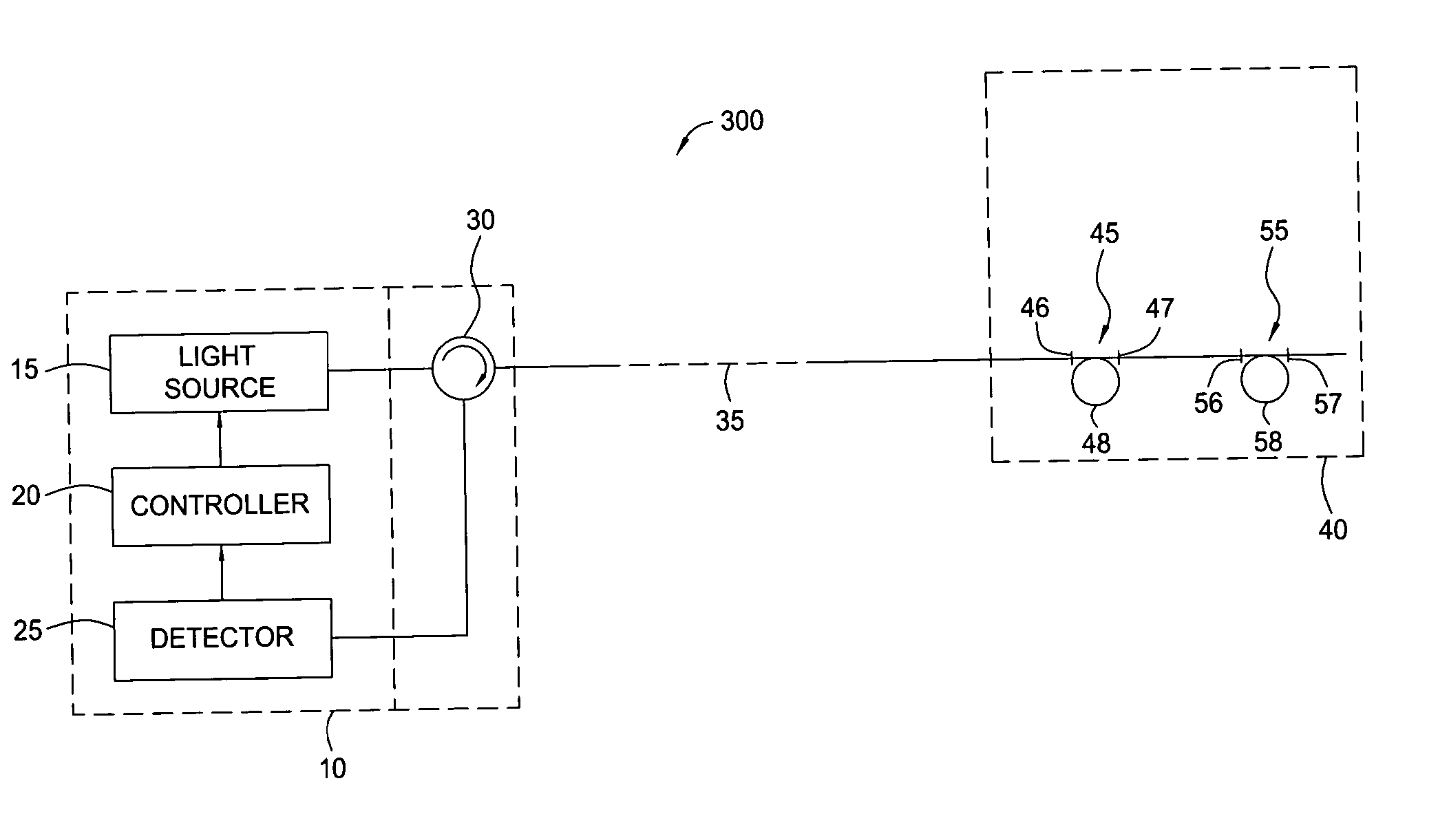
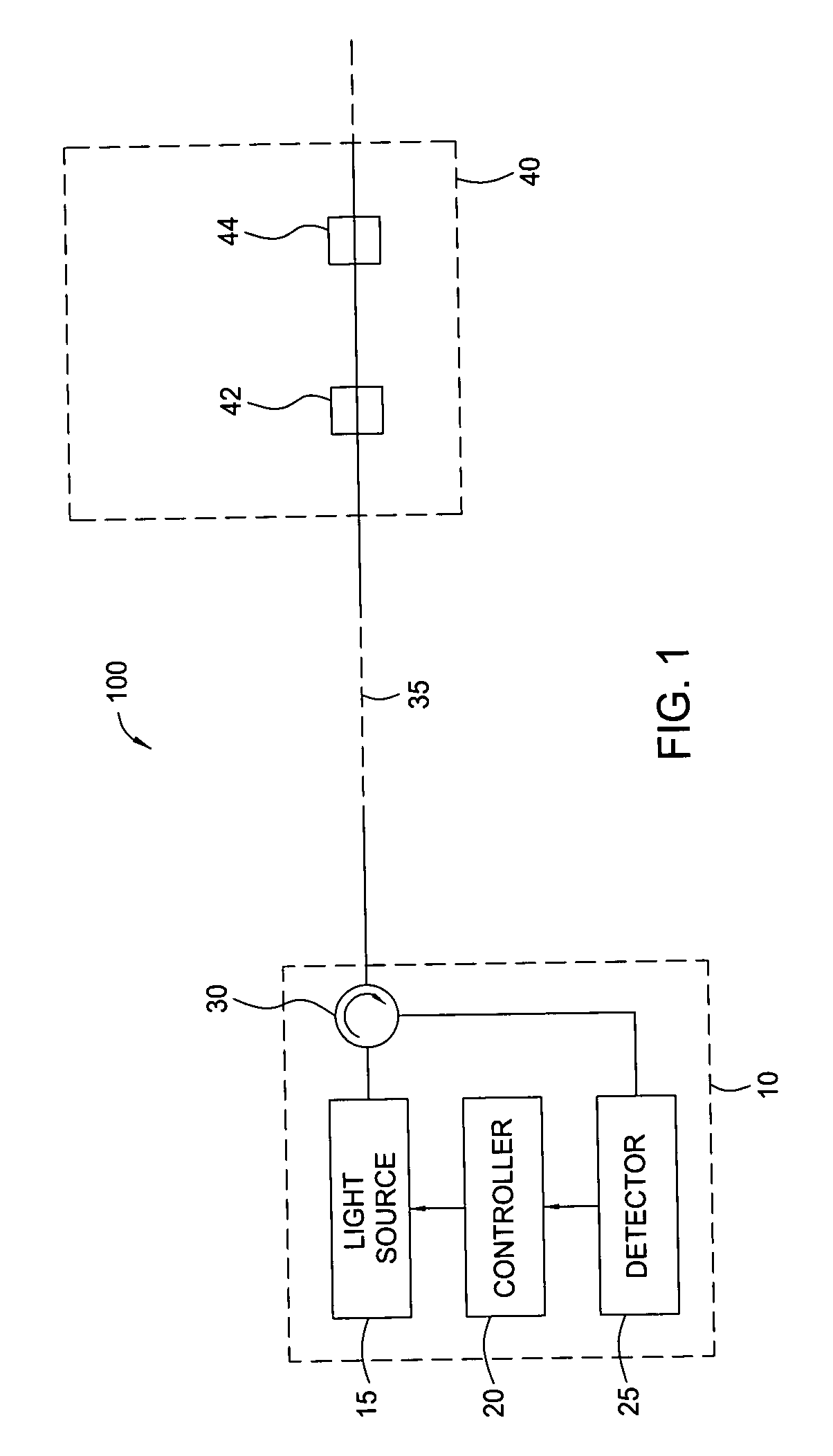
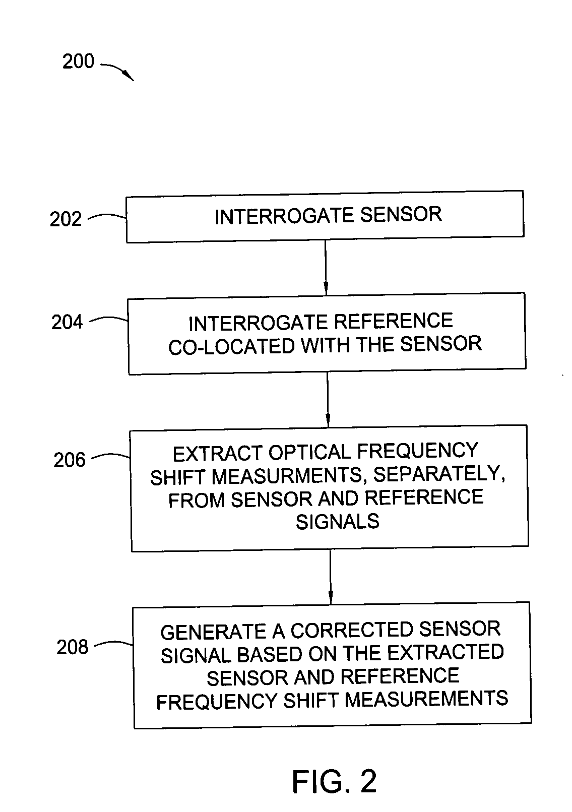
[0020] Embodiments of the present invention provide improved optical sensor systems and methods for eliminating or reducing the effects of frequency fluctuations in an interrogating light signal used to illuminate optical optical sensors such as Bragg grating sensors and optical interferometer sensors. The frequency fluctuations may be due to light source instabilities, changes to a light signal traveling through an optical fiber (or any other type optical waveguide) to a sensor, and / or other environmental conditions and effects. Interrogating light signal frequency fluctuations may result in optical sensor output variations and unwanted noise. However, embodiments of the present invention may be used to improve the accuracy and repeatability of optical sensor systems by allowing for the correction of frequency fluctuations through the use of reference devices co-located with sensors. Embodiments of the present invention may offer numerous advantages over prior art optical sensor sy...


PUM


Abstract

Embodiments of the present invention generally provide methods, apparatus, and systems for compensating for frequency fluctuations in source light used to interrogate an optical sensor. The optical sensor may be interrogated to generate a sensor signal. A reference device co-located with the optical sensor may also be interrogated to generate a reference signal. Optical parameters extracted from the reference signal may be used to correct parameters extracted from a sensor signal.

Description

BACKGROUND OF THE INVENTION [0001] 1. Field of the Invention [0002] Embodiments of the present invention generally relate to optical sensing systems and, more particularly, to compensating for frequency fluctuations in source light used to interrogate optical sensors. [0003] 2. Description of the Related Art [0004] Optical sensors can offer numerous advantages over conventional electrical and / or electromechanical sensing devices. For example, optical sensors typically have greater resistance to electromagnetic interference (EMI) than other types of sensors. Additionally, optical sensors tend to be small, lightweight, and physically robust. Consequently, optical sensors are commonly used in applications requiring resistance to a variety of harsh environmental conditions, such as downhole sensing applications. [0005] Most optical sensors operate under the same basic principles. A sensitized region along an optical fiber is exposed to an environmental condition that modulates a light s...

Claims


Application Information

Patent Timeline
IPC IPC(8): G01B9/02
CPCG01B9/02007G01B2290/60G01B2290/25G01B9/0207
Inventor RONNEKLEIV, ERLEND
Owner OPTOPLAN
Why Eureka
Try Eureka