Method and apparatus for measuring photoelectric conversion device, and process and apparatus for producing photoelectric conversion device

Inactive Publication Date: 2005-09-20
CANON KK
View PDF6 Cites 43 Cited by
  • Summary
  • Abstract
  • Description
  • Claims
  • Application Information

AI Technical Summary

Benefits of technology

[0025]Another object of the present invention is to provide a measuring method which enables to precisely measure the current-voltage characteristics of a photoelectric conversion device even under condition where light whose intensity is unstable such as pulsed light or the sunlight is irradiated.
[0026]A further object of the present invention is to provide a measuring apparatus which enables to precisely measure the current-voltage characteristics of a photoelectric conversion device even under condition where light whose intensity is unstable such as pulsed light or the sunlight is irradiated.

Problems solved by technology

As a result, there was obtained findings that it is not sufficient merely to prolong the time interval for the voltage applied to the inspective photoelectric conversion device with consideration of the responsibility thereof to the charge-and-discharge but it is necessary to take a proper measure for the difference between the light responsibility of a reference device and that of the Inspective photoelectric conversion device.
However, in the case where an artificial light source of pulsed light is used or the sunlight is used, because the irradiance is not constant, it is necessary to detect the irradiance by the reference device simultaneously with the measurement of the current-voltage characteristics of the inspective photoelectric conversion device.

Method used


Image

  • Method and apparatus for measuring photoelectric conversion device, and process and apparatus for producing photoelectric conversion device
  • Method and apparatus for measuring photoelectric conversion device, and process and apparatus for producing photoelectric conversion device
  • Method and apparatus for measuring photoelectric conversion device, and process and apparatus for producing photoelectric conversion device

Examples


example 1

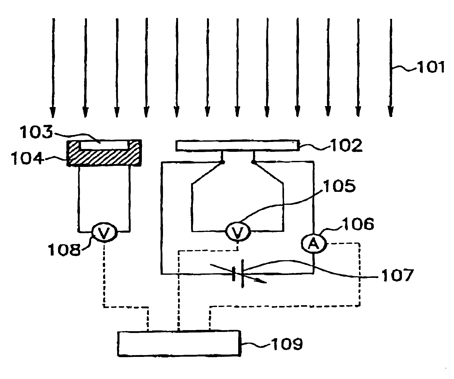
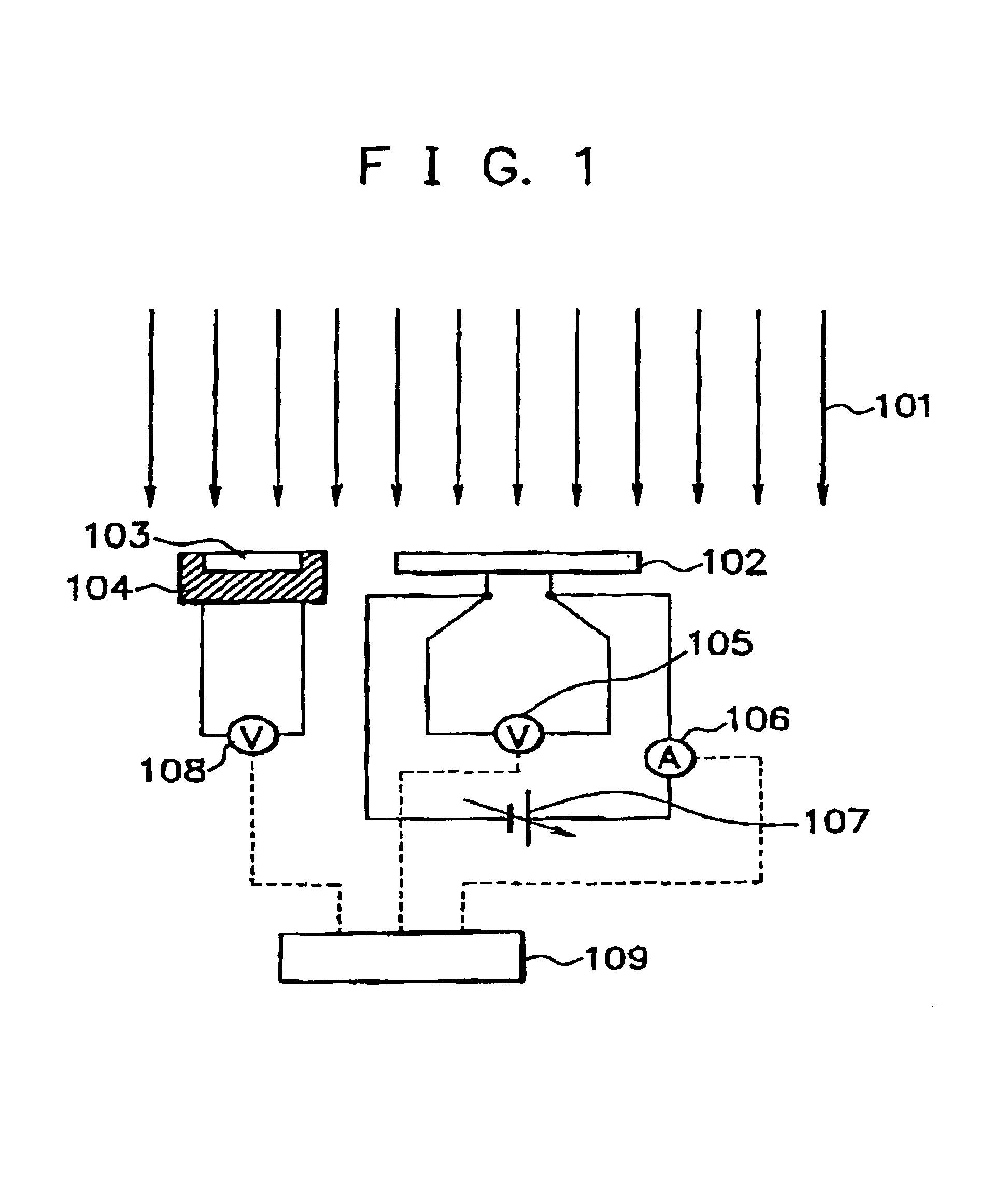
[0152]This example describes an embodiment in that in accordance with the measuring method of the present invention using the measuring system shown in FIG. 1, a photoelectric conversion device to be inspected (hereinafter referred to as “inspective photoelectric conversion device”) is measured with respect to current-voltage characteristics thereof.

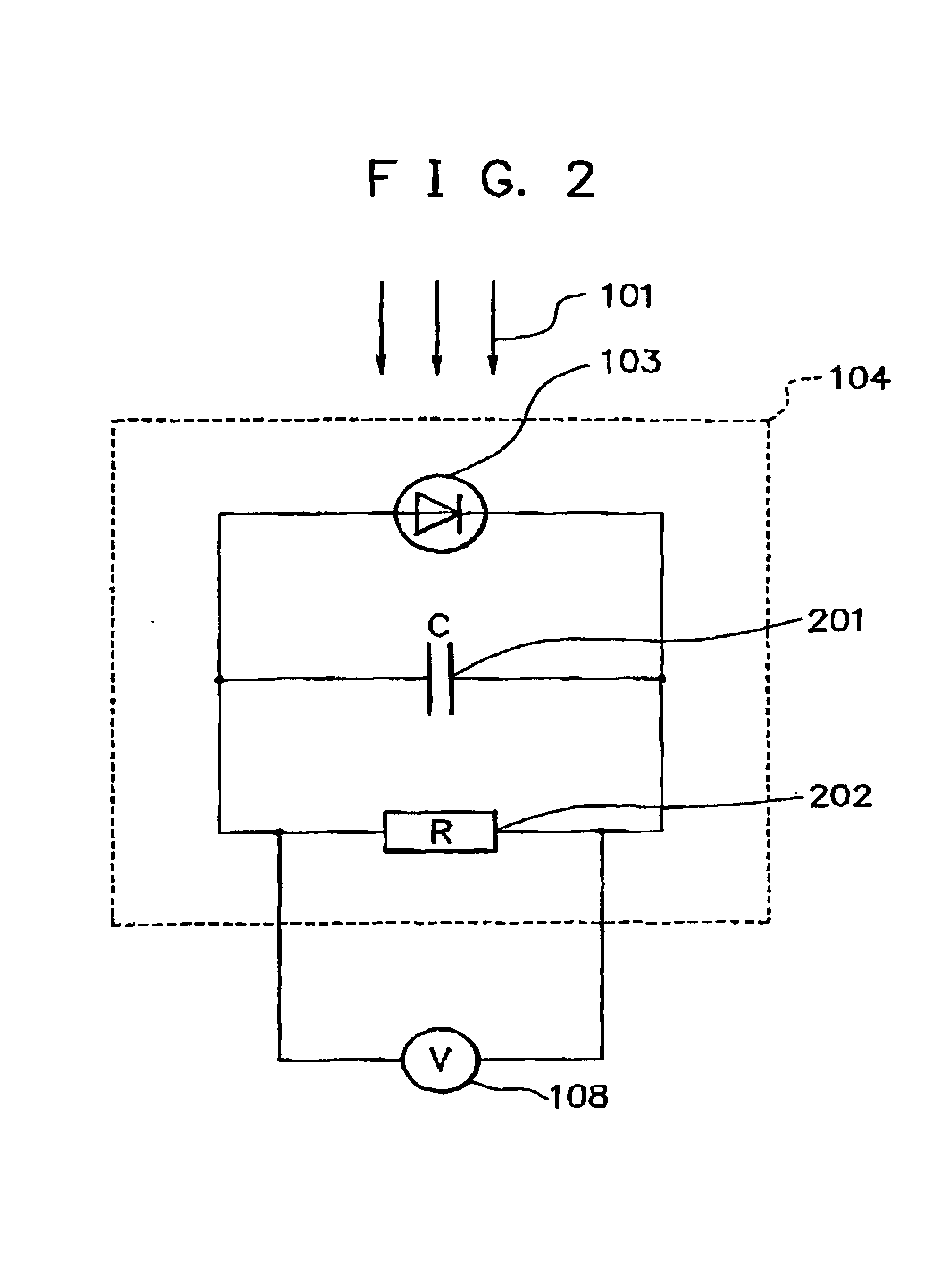
[0153]In the following, the measuring procedures to measure the inspective photoelectric conversion device will be detailed chiefly with reference to FIGS. 1, 2 and 5.

[0154]As the inspective photoelectric conversion device 102, there is used a triple a-Si / a-SiGe / a-SiGe type solar cell module having an aperture area of about 120 cm×35 cm and an outer shape of about 140 cm×42 cm, prepared by providing five triple a-Si / a-SiGe / a-SiGe type solar cells comprising a top cell having a p-i-n junction in which an amorphous silicon (a-Si) is used as an i-type semiconductor layer, a middle cell having a p-i-n junction in which an amorphous silicon-g...

example 2

[0194]As well as in Example 1, the measurement of a triple type solar cell module which is the same as the triple type solar cell module used in Example 1 was carried out using the measuring system shown in FIG. 1, except that the RL integrating circuit shown in FIG. 3 was used instead of the RC integrating circuit used as the irradiance detection circuit in which the reference cell is used in Example 1.

[0195]In this example, in order to make the light responsive time constant of the irradiance detection circuit to come closer to that of the triple type solar cell module, the time constant of RL integrating circuit was adjusted in the same manner as in Example 1.

[0196]As a result, there was obtained a smooth I-V curve after the correction as well as in Example 1.

[0197]A portion of the I-V curve in the vicinity of the Isc side which was considered to be capable of being approximated by a straight line was linearly approximated by the least square method, and a standard deviation of d...

example 3

[0198]As well as in Example 1, the measurement of a triple type solar cell module which is the same as the triple type solar cell module used in Example 1 was carried out using the measuring system shown in FIG. 1, except that a photoelectric conversion device was used instead of the RC integrating circuit used as the irradiance detection circuit in which the reference cell is used in Example 1.

[0199]As the photoelectric conversion device, there was used a triple type solar cell whose constitution is the same as that of the triple type solar cell of the triple type solar cell module used in Example 1. Provided that in this triple type solar cell (hereinafter referred to as “time constant-adjusting cell”), a shield was provided so as to prevent light from being impinged therein. The time constant-adjusting cell is connected with the reference cell of the irradiance detection circuit in parallel connection in a forward direction such that the positive electrodes of the two cells are c...


PUM

PropertyMeasurementUnit
temperatureaaaaaaaaaa
irradianceaaaaaaaaaa

Abstract

A measuring method for measuring current-voltage characteristics of a photoelectric conversion device by irradiating light to said photoelectric conversion device and a reference device corresponding to said photoelectric conversion device at the same time while detecting an irradiance of said light using said reference device, characterized in that a light responsive time constant of a irradiance detection circuit in which said reference device is used is adjusted so that said light responsive time constant of said irradiance detection circuit comes closer to a light responsive time constant of said photoelectric conversion device. An apparatus for practicing said measuring method.

Description

BACKGROUND OF THE INVENTION[0001]1. Field of the Invention[0002]The present invention relates to a measuring method for measuring current-voltage characteristics of a photoelectric conversion device such as solar cell, photovoltaic element or photosensor under irradiation of light. In the present invention, said photoelectric conversion device includes a photoelectric conversion apparatus prepared by connecting a plurality of photoelectric conversion devices in series or parallel connection. The present invention includes a process and an apparatus for producing a photoelectric conversion device.[0003]2. Related Background Art[0004]The photoelectric conversion characteristics (for example, efficiency, Voc, Isc, and fill-factor) of a photoelectric conversion device such as solar cell, photovoltaic device or photosensor can be obtained by measuring current-voltage characteristics thereof under irradiation of light. The measuring method in this case includes a measuring method wherein ...

Claims


Application Information

Patent Timeline
Patent Type & Authority Patents(United States)
IPC IPC(8): G01M11/00G01J1/00G01R31/00G01R31/26H01J40/14H01J40/00H01L31/04H01M14/00
CPCH02S50/10G01R31/2603Y02E10/50
Inventor MATSUYAMA, JINSHO
Owner CANON KK
Why Eureka
Try Eureka