Autonomous transport system

a transportation system and autonomous technology, applied in the direction of climate sustainability, railway tracks, locomotives, etc., can solve the problems of not being used as a passenger urban, not being able to run horizontally, and known vertical transportation devices such as elevators using cables and engine rooms,

Inactive Publication Date: 2002-08-13
SERRANO JORGE
View PDF21 Cites 79 Cited by
  • Summary
  • Abstract
  • Description
  • Claims
  • Application Information

AI Technical Summary

Benefits of technology

Accordingly, it is one object of the present invention to provide an autonomous transport system which is capable of overcoming the transport handicaps shown in prior art devices, being able to run on horizontal, highly sloped and vertical tracks with no speed degrading and capable of keeping a plurality of vehicle units in autonomous movement and individual full stop, with guaranteed non-slipping action on any of the mentioned tracks.
It is another object of the present invention to provide a vehicle that is able to run on horizontal, highly sloped or vertical without risk of slipping and with absolute security for the people and goods transported in it.
It is a further object of the present invention to provide a transportation method for people and goods, carried out by the autonomous transport system of the present invention, and particularly for solving densely populated city transportation.

Problems solved by technology

Known vertical transport devices such as elevators use cables and engine rooms and have height limitations.
Transportation devices for steep slopes also use cables or racks and their cabin does not keep a horizontal position while moving.
Therefore these may not be used as a passenger urban train
The mentioned device is capable of running horizontally or on slight slopes but is not capable of running in vertical tracks, just as a conventional train or a bus when running under 100 mph.
Although a pendulum is mentioned, the latter is only used for keeping lateral balance but does not allow to keep the vehicle's horizontal overall position.
The driving mechanism of the mentioned patent is different from the present invention since it is not based on a combination of a pair of slipping-free guides with slipping-free wheels and does not guarantee equilibrium under all load conditions because its wheels do not increase pressure against the rail guides when the slope gets steeper, and therefore does not assure free of slippage rolling.
However, the units may not travel vertically and therefore may not link several floors of a building or the latter with another premises.
The invention of the U.S. patent is directed to small load transport and may not be applied to public transport vehicles because it is designed for handling small weights and is not capable of carrying people, particularly in vertical and sloped tracks, because the springs cannot guarantee that the friction between the wheels and the rails will be big enough to avoid slippage.
Furthermore, the pins described in the U.S. patent would immediately wear out or even brake under heavy load acceleration or sudden stop.
Therefore the mentioned patent lacks of the basic features for solving public transportation.
However, the units are not autonomous since all the chain is driven by one or more central engines and may only be used in low speed applications such as shoppings, airports, etc.
However the system seems to be unable to run on vertical tracks, it may not handle autonomous car cabins and, unlike the present invention, is driven by cables.
However, the mentioned patent does not describe a multiple autonomous car system that may run on horizontal, sloped or vertical guides and replace conventional public transportation.

Method used


Image

  • Autonomous transport system
  • Autonomous transport system
  • Autonomous transport system

Examples


Embodiment Construction

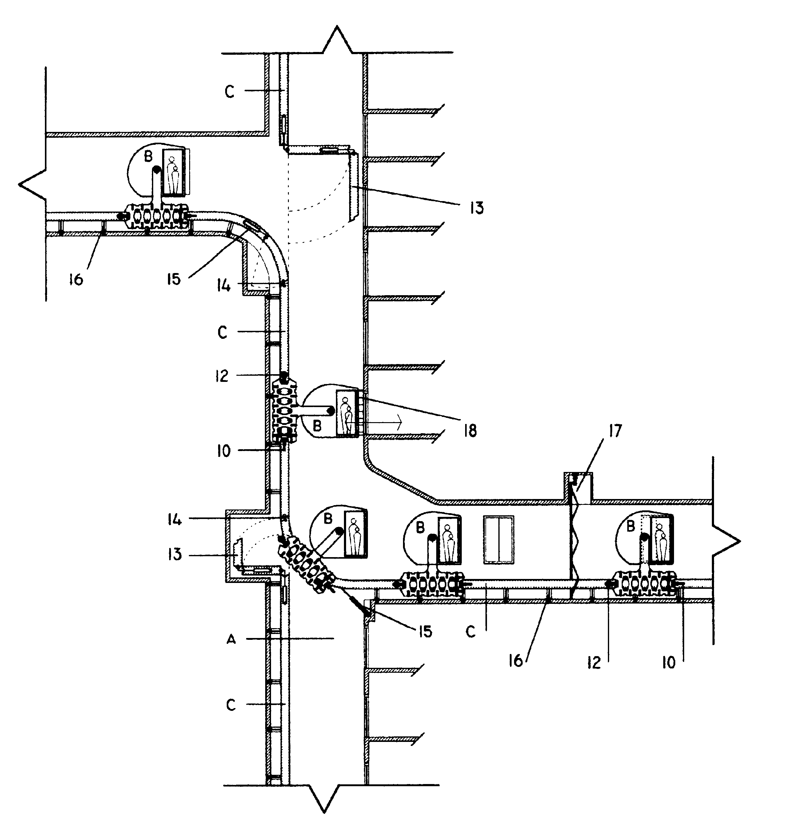
The Autonomous Transport System (A.T.S) of the present invention is formed by four main sub-systems:

A) Channel Sub-system (CSS)

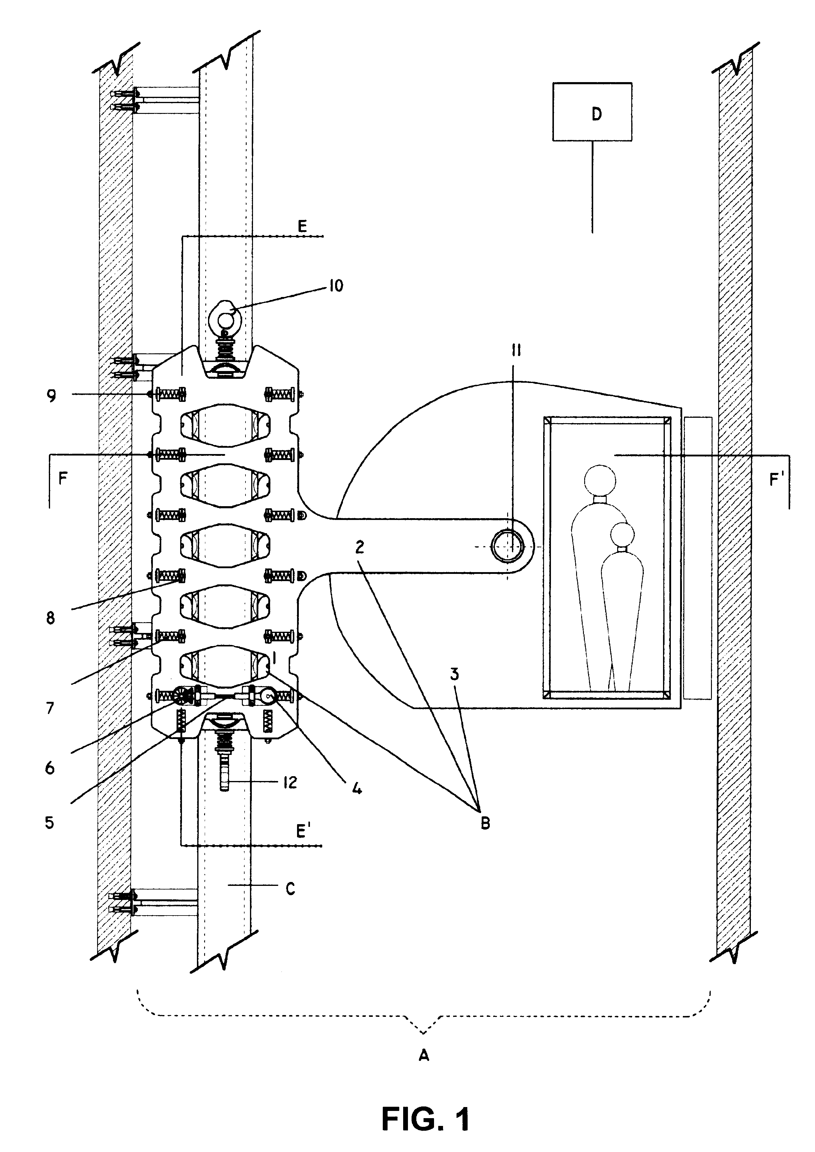
In FIG. 1, reference A shows the space or channel through which the transport unit may move. This channel can be interior or exterior to a particular premise, depending on its use and location. It will be defined as being interior when located inside of a building, in constructions or urban settlements or in underground sites, and exterior, when the wheel guides and the vehicle are to be located in an open space, outdoors.

B) Vehicle Sub-system (VSS)

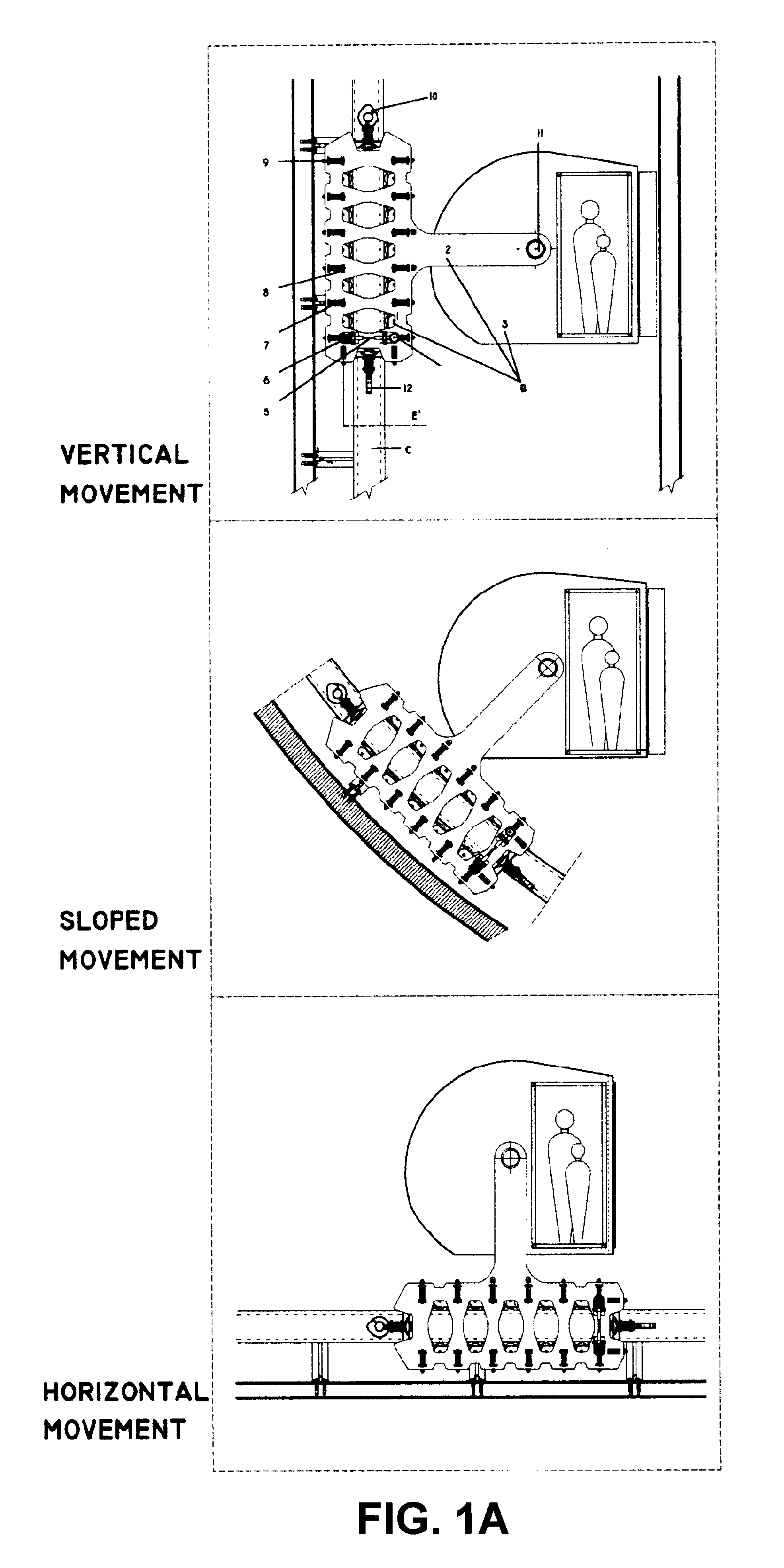
In FIG. 1, reference B shows the elements which form the vehicle unit. The unit is powered by electric energy and moves on wheel guides, in any direction: vertical, horizontal or slanted, regardless of the slope; in either direction. The overall runway is controlled from the Central Control Station and the desired stops may be controlled by pre-programmed schedules or else may be selected by the passengers from th...


PUM


Abstract

An autonomous transport system is disclosed, formed by four main subsystems: a channel subsystem; a vehicle subsystem; a wheel guide subsystem and central control station subsystem. The system is designed for the transportation of people or goods, to be used in tall buildings and in small and large scale urban environments. It comprises unitary vehicles that may move in different directions: horizontal, steeply sloped and also vertical tracks, thanks to novel traction wheel assemblies that roll on carefully designed wheel tracks. The system's cabin maintains the horizontal level / position regardless of the changes of track direction or slanting thanks to pendulum based automatic level control and may rotate up to 180° under normal conditions and even a full 360° turn respect to the wheel assembly in space restricted positions. The cabin is mounted on a cantilever, thereby displacing its center of gravity respect of the wheel guides. Thus, a lever action is established, which presses the wheels against the wheel tracks and therefore enough frictional resistance is obtained so as to avoid wheel slippage on the wheel tracks. The vehicles are moved by non-polluting, electric drives that move and stop them with high energy savings. The vehicle runways are designed taking in account safety features against fire hazards. Several vehicles may be used at the same time and on the same track and may run individually or in groups, conforming a train. The system allows for vehicles to be parked in bypassed positions or else they may be disengaged from the convoy to be used individually.

Description

The present application claims priority of the Argentine patent application No. P00 01 00142, which was filed on Jan. 13, 2000, in the name of the same applicant.The present invention relates to a transport device for horizontal, sloped and vertical movement, for carrying people or goods.The present invention is particularly adequate for being used in large buildings (not only tall but also wide spread ones), and in small and large scale urbanization projects. The system of the present invention can interact with other systems. It may replace trains in flat ground, elevated monorails, cogwheel, rack railways and the well known elevator, covering all the ground transport means that run on rails. It may work either as an individual vehicle (in a building or in a group of buildings), or forming a convoy, by engaging individual units. It may act on steep slopes, vertical or horizontal guides or channels.When transport interference appears within the city, the mobile device of the presen...

Claims


Application Information

Patent Timeline
Patent Type & Authority Patents(United States)
IPC IPC(8): B61B13/00B66B9/00B66B1/14B66B11/04B66B1/24
CPCB61B13/00B66B9/00B66B11/0476Y02T30/00
Inventor SERRANO, JORGE
Owner SERRANO JORGE
Why Eureka
Try Eureka