
Torque detector and controls for prohibiting the operation of an electric motor on a hybrid vehicle when the driving torque of the vehicle exceeds a predetermined value during start-up

a technology of torque detector and control, which is applied in non-electric variable control, process and machine control, instruments, etc., can solve the problems of high cost, troublesome former system, and difficulty in maintaining the durability of the brush

Inactive Publication Date: 2002-08-20
HONDA MOTOR CO LTD
View PDF16 Cites 51 Cited by
  • Summary
  • Abstract
  • Description
  • Claims
  • Application Information

AI Technical Summary

Benefits of technology

On the other hand, when the wheels slip at the time of starting the vehicle on a road surface having a low coefficient of friction (e.g., on a slippery snowy road or the like), the driving load will not operate so much on the wheels, with the result that the driving torque of the wheels becomes small.
In this manner, the electric motor is operated only in a condition in which the effect of starting assistance is desired. The inefficient operation of the electric motor can therefore be prevented.

Problems solved by technology

In addition, an inverter circuit becomes necessary, resulting in a higher cost.
However, if the DC brush motor is used always at the time of starting the vehicle, the durability of the brush will become a problem.
However, the former system is troublesome because the operation of the switch becomes necessary.
It follows that the electric motor is inefficiently operated.
Even when the wheels slip at the time of starting the vehicle on a road surface having a high coefficient of friction, a relatively large driving load is applied to the wheels due to the friction between the wheels and the road surface.
On the other hand, when the wheels slip at the time of starting the vehicle on a road surface having a low coefficient of friction (e.g., on a slippery snowy road or the like), the driving load will not operate so much on the wheels, with the result that the driving torque of the wheels becomes small.

Method used


Image

  • Torque detector and controls for prohibiting the operation of an electric motor on a hybrid vehicle when the driving torque of the vehicle exceeds a predetermined value during start-up
  • Torque detector and controls for prohibiting the operation of an electric motor on a hybrid vehicle when the driving torque of the vehicle exceeds a predetermined value during start-up
  • Torque detector and controls for prohibiting the operation of an electric motor on a hybrid vehicle when the driving torque of the vehicle exceeds a predetermined value during start-up

Examples


Embodiment Construction

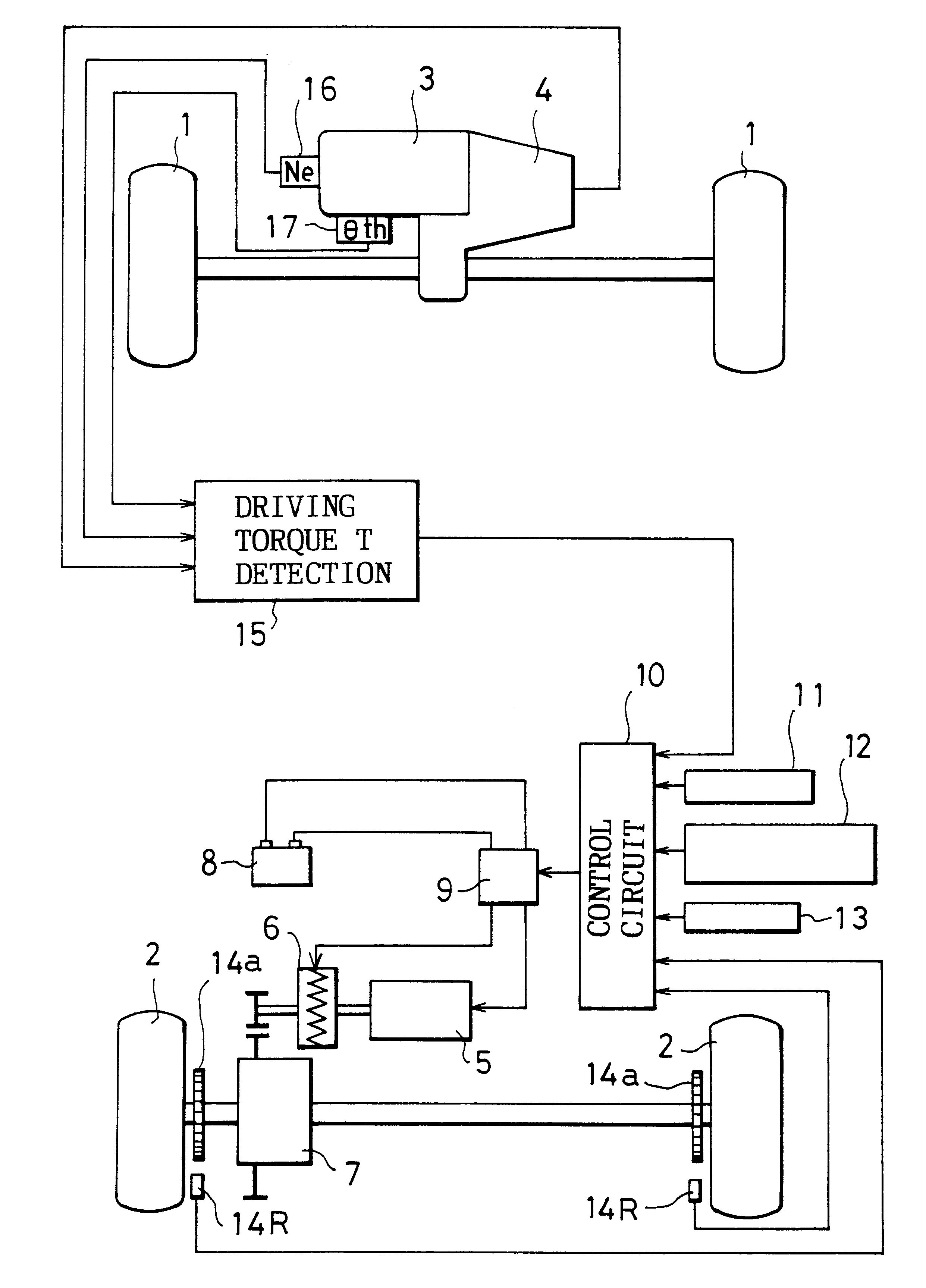
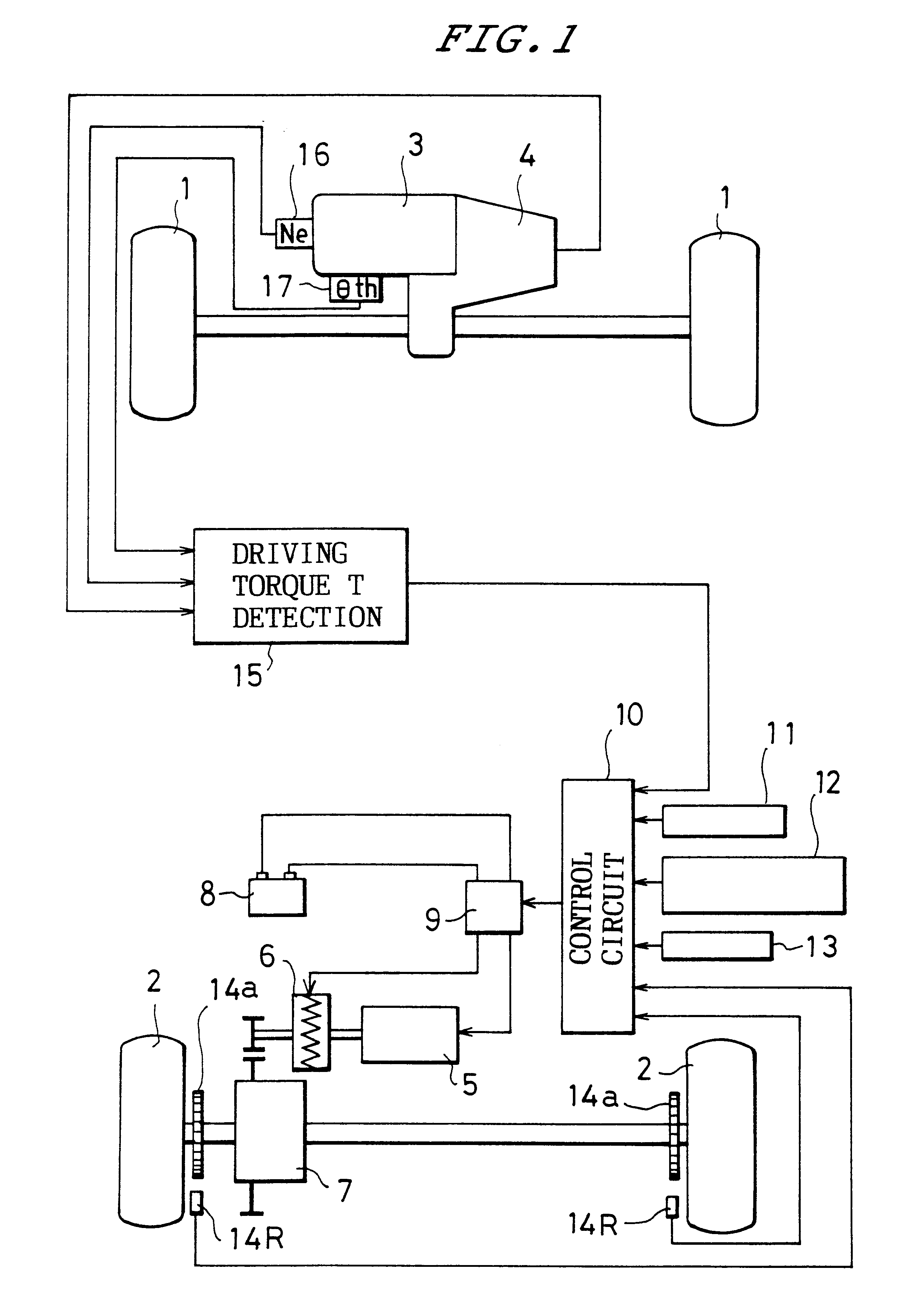
The embodiment in FIG. 1 shows a four-wheeled vehicle having a pair of front wheels 1 and a pair of rear wheels 2, respectively. The pair of right and left front wheels 1, 1 are driven by an engine 3 via a transmission 4. The pair of right and left rear wheels 2, 2 are driven by an electric motor 5 via a clutch 6 and a differential gear 7.

The electric motor 5 is constituted as a direct-current (DC) brush motor and is connected to a vehicle-mounted battery 8 via a switching circuit 9 in which is built a circuit for switching between forward running and reverse running. The switching circuit 9 is controlled to be switched on and switched off by a signal from the control circuit 10. When the switching circuit 9 is switched on, the electric motor 5 is operated and also the clutch 6 is engaged so that the rear wheels 2 can be driven by the electric motor 5. The circuit for switching between forward running and reverse running, which is built in the switching circuit 9, is controlled for ...


PUM


Abstract

Either the front wheels and rear wheels of a front wheel- and rear wheel-drive vehicle are driven by an engine and the other thereof are driven by an electric motor. The electric motor is operated when the vehicle starts. A driving torque detecting circuit detects a driving torque of wheels to be driven by the engine. Control circuit prohibits the operation of the electric motor when the driving torque to be detected at vehicle start-up exceeds a predetermined value.

Description

1. Field of the InventionThe present invention relates to a front wheel- and rear-wheel drive vehicle in which either the front wheels or the rear wheels are driven by an engine and the other thereof are driven by an electric motor.2. Description of the Related ArtConventionally, there is known a kind of vehicle in which an alternating-current (AC) motor is used as an electric motor and in which the electric motor is made operable over the entire range of vehicle speed through an inverter control (see Japanese Published Unexamined Patent Application No. 159502 / 1991).In order to cover the entire range of the vehicle speed as in the above-described prior art, it is necessary to employ an electric motor having a large output. In addition, an inverter circuit becomes necessary, resulting in a higher cost.By the way, if an arrangement is made to operate the electric motor only at the time of starting the vehicle in order to limit the purpose of using the electric motor to the assistance ...

Claims


Application Information

Patent Timeline
IPC IPC(8): B60L11/12B60K6/04B60K6/00B60L11/02B60K17/34B60K17/356B60K6/485B60K6/52B60L50/15B60L50/16B60W10/02B60W10/08B60W20/00B60W20/10
CPCB60K6/52B60K17/356B60L11/12B60W10/02B60W10/08B60L2240/16B60L2240/443Y10S903/916B60W20/00B60W2510/0657B60W2520/105Y02T10/6265Y02T10/7077Y10S903/946B60L50/15Y02T10/62Y02T10/7072B60W30/18027B60W20/11
Inventor ARAI, KENTAROU
Owner HONDA MOTOR CO LTD
Features
  • Generate Ideas
  • Intellectual Property
  • Life Sciences
  • Materials
  • Tech Scout
  • Unparalleled Data Quality
  • Higher Quality Content
  • 60% Fewer Hallucinations
Learn More