DC-to-DC converter and electronic device using the same

a converter and electronic device technology, applied in the direction of dc-dc conversion, power conversion systems, instruments, etc., can solve the problems of large circuit size, reduced cost, and reduced cos

Inactive Publication Date: 2002-08-20
MURATA MFG CO LTD
View PDF3 Cites 16 Cited by
  • Summary
  • Abstract
  • Description
  • Claims
  • Application Information

AI Technical Summary

Problems solved by technology

In the DC-to-DC converter 1 shown in FIG. 10, because the error amplifier circuit 4, the triangular wave generating circuit 5, the PWM comparator 6, etc., are included, the size of the circuit becomes large and a problem occurs in that reduction in cost becomes difficult.
Furthermore, since the size of the circuit is large, the DC-to-DC converter is often assembled by using ICs, and in that case, as the size increases and the cost rises, there is a problem in that reduction in cost and also reduction in size becomes difficult.

Method used


Image

  • DC-to-DC converter and electronic device using the same
  • DC-to-DC converter and electronic device using the same
  • DC-to-DC converter and electronic device using the same

Examples


Embodiment Construction

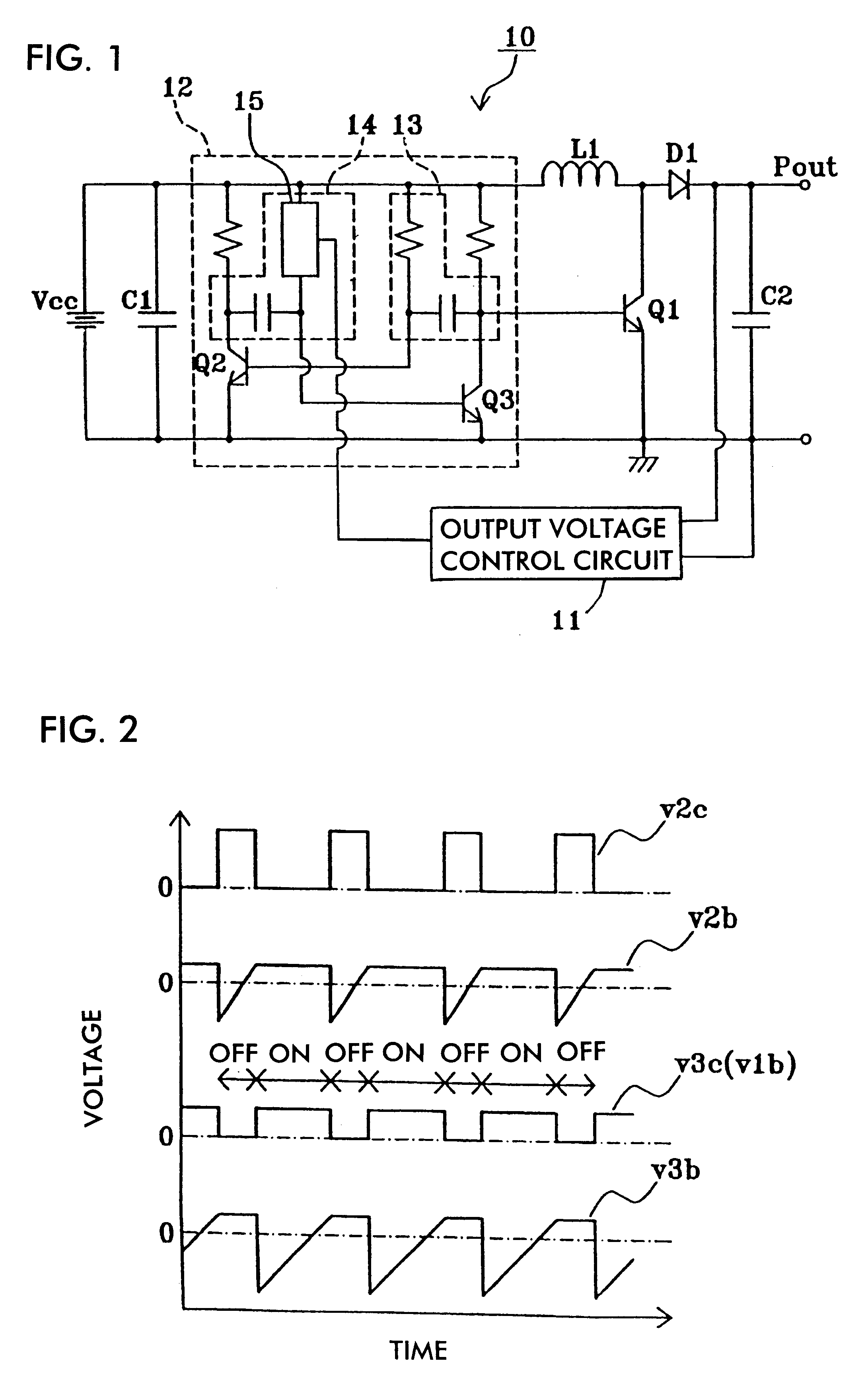
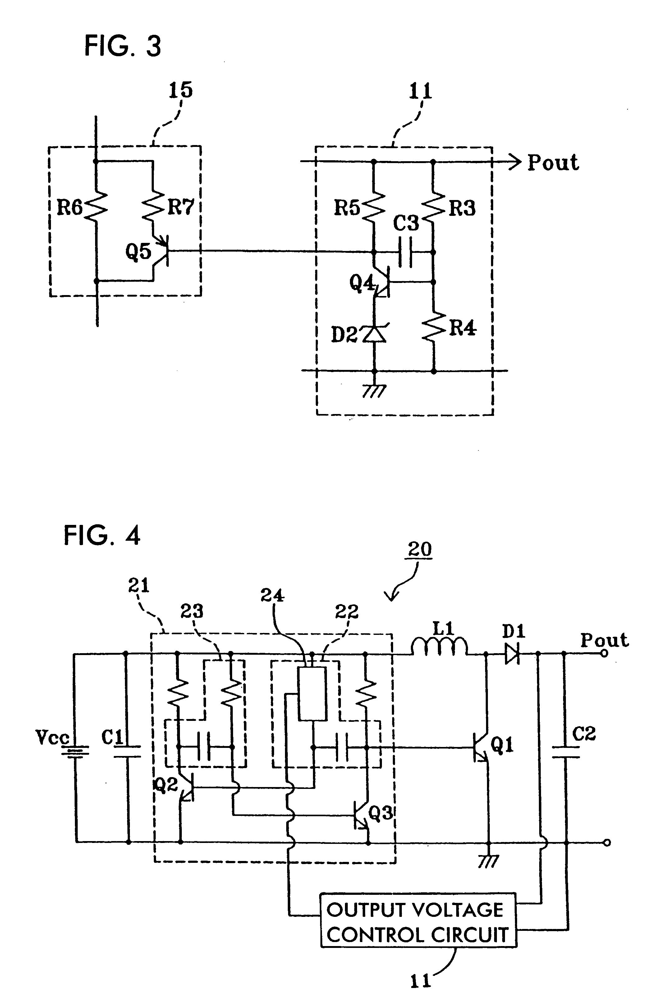
FIG. 1 is a circuit diagram of a DC-to-DC converter according to an embodiment of the present invention. In FIG. 1, the same reference numerals are assigned to the same or equivalent portions as in FIG. 10, and their description is omitted.

In FIG. 1, the DC-to-DC converter 10 is provided with an output voltage control circuit 11 and an astable multivibrator 12 instead of the drive circuit 2, the reference voltage generating circuit 3, the error amplifying circuit 4, the triangular wave generating circuit 5, the PWM comparator 6, and the resistors R1 and R2 shown in FIG. 10. The astable multivibrator 12 comprises a transistor Q2, a first time constant circuit 13 formed of a resistor and a capacitor, which determines the OFF-period of the transistor Q2, a transistor Q3, and a second time constant circuit 14 comprising a variable impedance circuit 15 and a capacitor, which determines the OFF period of the transistor Q3. The collector of the transistor Q3 is connected to the base of a t...


PUM


Abstract

A DC-to-DC converter is provided with an astable multivibrator containing a first time constant circuit for setting an ON period of an output and a second time constant circuit for setting an OFF period of the output, and provided with a switching element controlled by the output. The output voltage is controlled by changing the duty ratio of the astable multivibrator in accordance with the output voltage.

Description

1. Field of the InventionThe present invention relates to a DC-to-DC converter and an electronic device using the DC-to-DC converter.2. Description of the Related ArtFIG. 10 is a circuit diagram of a conventional DC-to-DC converter. In FIG. 10, the DC-to-DC converter comprises a DC power supply Vcc, an inductance element L1, a diode D1 as a rectifying element, a transistor Q1 as a switching element, resistors R1 and R2, capacitors C1 and C2, a drive circuit 2, a reference voltage generating circuit 3, an error amplifier circuit 4, a triangular wave generating circuit 5, a PWM comparator 6, and an output terminal Pout.The DC power supply Vcc is connected to one end of the inductance element L1, and the other end of the inductance element L1 is connected to the collector of the transistor Q1 and the anode of the diode D1. The cathode of the diode D1 is connected to the output terminal Pout. The emitter of the transistor Q1 is grounded. The capacitor C1 is connected in parallel to the ...

Claims


Application Information

Patent Timeline
Patent Type & Authority Patents(United States)
IPC IPC(8): H02M3/04H02M3/156H02M3/155
CPCH02M3/1563
Inventor KUNII, SHINGOSANO, NAOTO
Owner MURATA MFG CO LTD
Why Eureka
Try Eureka