
Liquid crystal display device and associated fabrication method

a technology of liquid crystal display and fabrication method, which is applied in static indicating devices, instruments, non-linear optics, etc., can solve the problems of poor response of tn mode, narrow viewing angles, and narrow viewing angles through which the viewer can see images properly

Inactive Publication Date: 2002-08-20
TOSHIBA MATSUSHITA DISPLAY TECH
View PDF16 Cites 102 Cited by
  • Summary
  • Abstract
  • Description
  • Claims
  • Application Information

AI Technical Summary

Problems solved by technology

The TN mode, however, has the drawback of poor response.
Another disadvantage of the TN mode is that viewing angles, that is, angles through which the viewer can see images properly are narrow.
For this reason, such TN mode is unacceptable for liquid crystal display systems that operate at high speed to provide animatic images or require good angular viewability when viewed in diagonal directions.
However, the response speed of the PDLC mode is as low as that of TN liquid crystal display devices.
Additionally, the PDLC mode provides a wide range of viewing angles but the viewing angles of the PDLC mode cannot be controlled in principle by a phase compensating layer like the TN mode.
These modes suffer from the critical problems of poor shock resistance and temperature characteristics and therefore have not been put to practical use.
The OCB liquid crystal display device presents a difficult problem.
That is, the device requires formation of the bend alignment state prior to image displaying, which is unfavorable for the following reason.
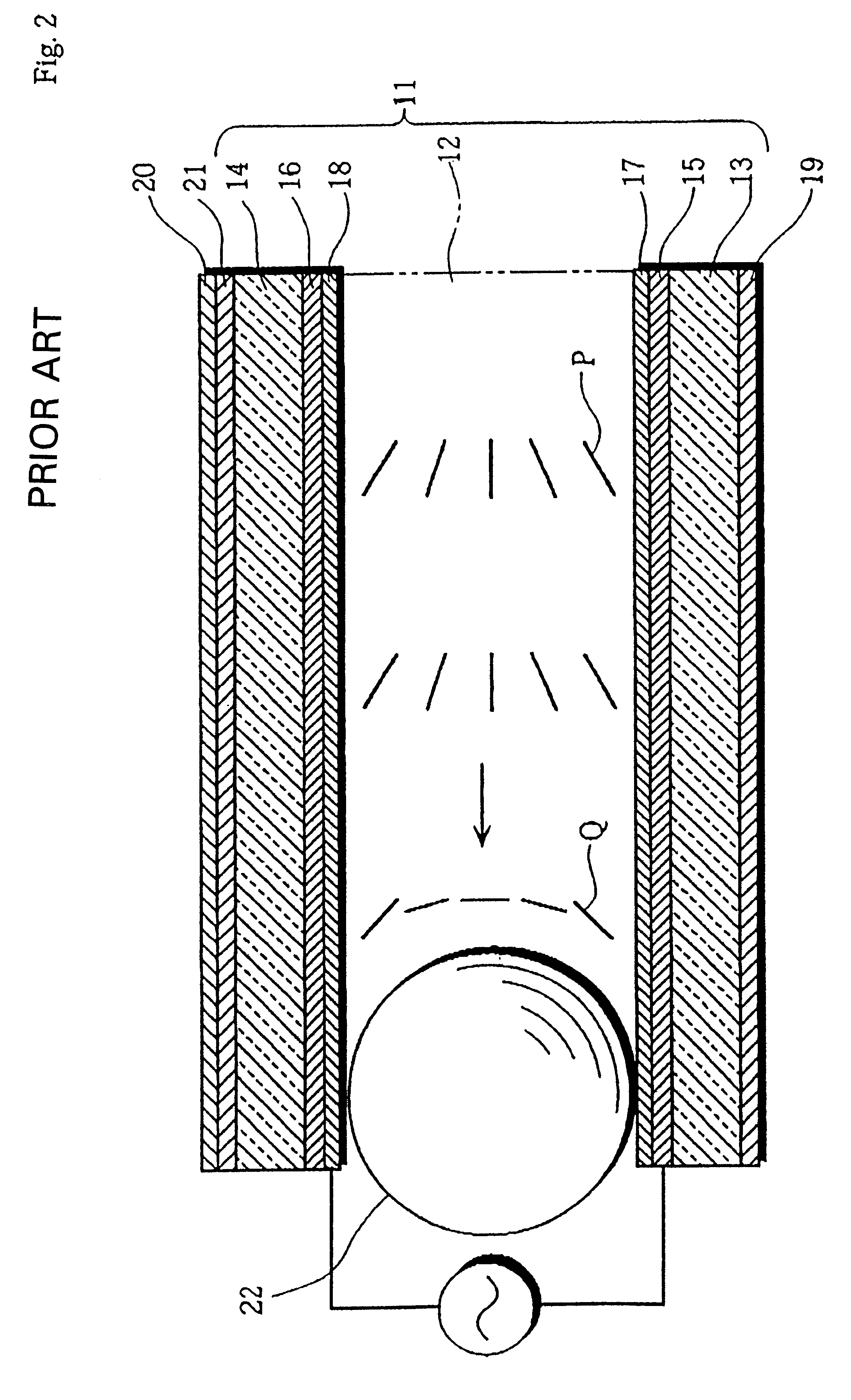
However, it takes more than tens of minutes to cause the transition when applying a voltage (several volts) that is low enough to avoid excessive load on the driving ICs.
This delay hinders practical use of the OCB liquid crystal display device.
In reality, however, fast response can not be necessarily achieved even if a director alignment similar to the bend alignment state is formed.
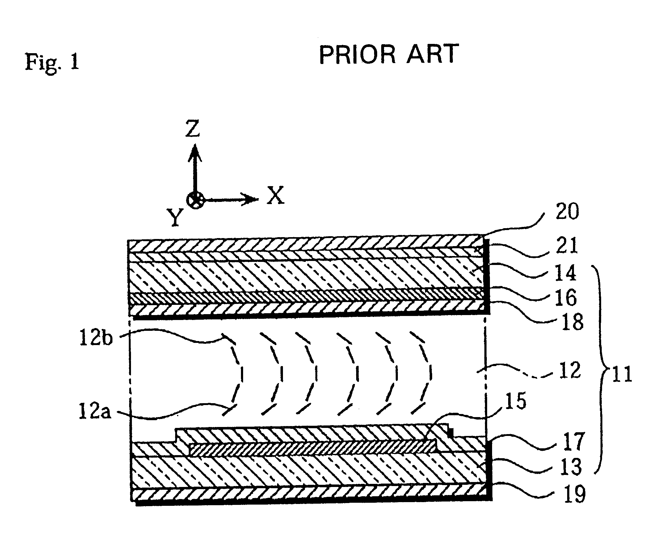
Although the above prior art OCB liquid crystal display device succeeds in providing wide viewing angles to a certain extent, the device still have difficulty in largely increasing the viewing angle within the plane where the Y and Z axes lie (see FIG. 1) by the phase compensating layer 21 alone and therefore the viewing angle characteristics vary significantly according to viewing directions.
However, the fabrication of such a phase compensating layer requires accurate control of the index of refraction in triaxial directions, so that where the OCB liquid crystal display device is applied to a large screen display system, it is extremely difficult to form such a compensating layer that possesses uniform properties throughout the display screen.
Although it is conceivable that hue shifts can be prevented by adjusting the voltage applied between the pixel and counter electrodes according to the color of light, such adjustment leads to an increased scale of the circuit and a higher production cost.
Liquid crystal display devices usually have a multitude of pixels, and if parts of the pixels do not have such transition, sound images cannot be displayed.

Method used


Image

  • Liquid crystal display device and associated fabrication method
  • Liquid crystal display device and associated fabrication method
  • Liquid crystal display device and associated fabrication method

Examples


embodiment 2

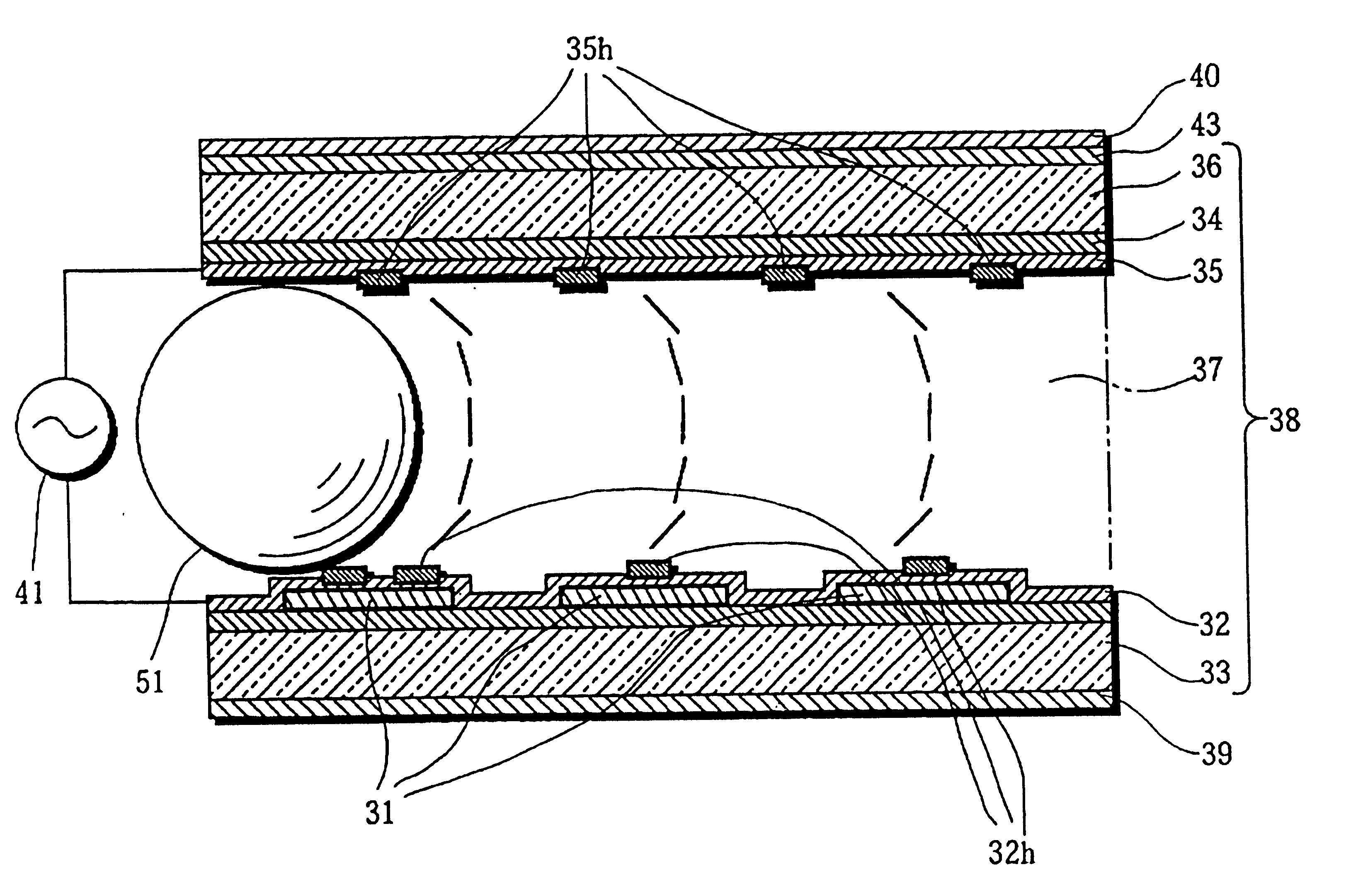
In lieu of the polyimide surface alignment agent capable of forming a pretilt angle of about 15.degree. used in Embodiment 1, a polyimide surface alignment agent of the prepolymerized type capable of forming a pretilt angle of about 70.degree. produced by Japan Synthetic Rubber Co., Ltd. under the number JALS-204 is used in Embodiment 2, for forming a high pretilt angle. The liquid crystal cell 38 having the large pretilt angle domains 32h, 35h formed on the alignment films 32, 35 was prepared and 5 V was applied for 2 seconds to the liquid crystal cell 38. After that, the transition occurred without fail. When a small amount of surface alignment agent that forms a substantially homeotropic structure of around 90.degree. was added, the transition readily occurred with low driving voltage.

embodiment 3

Another method for forming the large pretilt angle domains 32h, 35h similar to those in Embodiment 2 will be explained.

(1) First, a polyimide surface alignment agent of the prepolymerized type capable of forming a pretilt angle of about 5.degree. produced by Japan Synthetic Rubber Co., Ltd. under the number JALS-212 is applied to the transparent pixel electrodes 31 and the counter electrode 34. Then, the product is dried and sintered to form the alignment films 32, 35.

(2) A polyimide surface alignment agent of the prepolymerized type capable of forming a pretilt angle of 70.degree. and commercially available from Japan Synthetic Rubber Co., Ltd. under the number JALS-204 is printed on the alignment films 32, 35 at the positions corresponding to the transparent pixel electrodes 31 such that printed areas each having a diameter of about 10 .mu.m are arranged at a pitch of 100 .mu.m. Then, the product is dried and sintered to form the large pretilt angle domains 32h, 35h.

(3) Surface tr...

embodiments 1 to 3

In Embodiments 1 to 3 described above, the mixing ratio of the surface alignment agent for producing a large pretilt angle to the surface alignment agent for producing a small pretilt angle and the diameters of the large pretilt angle domains 32h, 35h, are not limited to the above figures but may be determined in accordance with the voltage and time required for the transition and with the liquid crystal material used. However, it should be noted that at least one large pretilt angle domain must be formed for every pixel. Transition is more likely to occur with the greater large pretilt angle and with the bigger difference between the large pretilt angle and the small pretilt angle. For this reason, the large pretilt angle may be in the range of from 15.degree. to 90.degree. and more preferably from 70.degree. to 90.degree., while the difference between the larger pretilt angle and the small pretilt angle may be 10.degree. or more. These ranges are, of course, not limitative of the ...


PUM

PropertyMeasurementUnit
pretilt angleaaaaaaaaaa
viewing angleaaaaaaaaaa

Abstract

A liquid crystal display device having a pixel electrode, a counter electrode, and a liquid crystal between the electrodes. Liquid crystal molecules in contact or near the respective opposed surfaces of the electrodes have specified pretilt angles as a result of the conditioning of those surfaces. When no voltage is applied, the liquid crystal is in a splay alignment state; applying voltage prior to image display causes a transition of transformation of the splay alignment state to a bend alignment state; image display is carried out under the bend alignment state. Transition from the splay alignment state to the bend alignment state is promoted by having a large pretilt angle domain formed on at least one of the electrode surfaces causing a larger pretilt angle of liquid crystal molecules than is present in a region surrounding the large pretilt angle domain.

Description

(1) Field of the InventionThe invention relates to liquid crystal display devices well suited for use in computer displays, television receivers and other industrial products and to methods for fabricating them. More particularly, the invention pertains to light-transmissive type and light-reflective type liquid crystal display devices capable of providing rapid response and a wide range of viewing angles and to fabrication methods thereof.(2) Description of the Related ArtThere have been practically used twisted-nematic (TN) liquid crystal display devices incorporating a nematic liquid crystal. The TN mode, however, has the drawback of poor response. Another disadvantage of the TN mode is that viewing angles, that is, angles through which the viewer can see images properly are narrow. Concretely, when diagonally viewing images in a TN liquid crystal display device, brightness and contrast decrease and gray scale inversion occurs. For this reason, such TN mode is unacceptable for li...

Claims


Application Information

Patent Timeline
Patent Type & Authority Patents(United States)
IPC IPC(8): G02F1/13G02F1/139G02F1/1333G02F1/1337
CPCG02F1/1395G02F1/133707G02F1/1337
Inventor HATTORI, KATSUJIISHIHARA, SHOICHIYAMAZOE, HIROSHI
Owner TOSHIBA MATSUSHITA DISPLAY TECH
Learn More