Vehicle occupant sensing system

a technology for sensing systems and vehicles, applied in pedestrian/occupant safety arrangements, special data processing applications, electric devices, etc., can solve problems such as inaccurate position measurements, complicated systems, and difficulty in installing and maintaining complex systems

Inactive Publication Date: 2002-08-27
SIEMENS VDO AUTOMOTIVE CORP
View PDF19 Cites 53 Cited by
  • Summary
  • Abstract
  • Description
  • Claims
  • Application Information

AI Technical Summary

Problems solved by technology

If the vehicle decelerates suddenly, such as when a collision occurs, occupants will tend to continue to move forward due to inertial effects.
The deployment of the airbag decreases the likelihood of serious injury for the occupants.
These systems are complex and expensive.
Often these complicated systems are difficult and time consuming to install and provide inaccurate position measurements.

Method used


Image

  • Vehicle occupant sensing system
  • Vehicle occupant sensing system
  • Vehicle occupant sensing system

Examples


Embodiment Construction

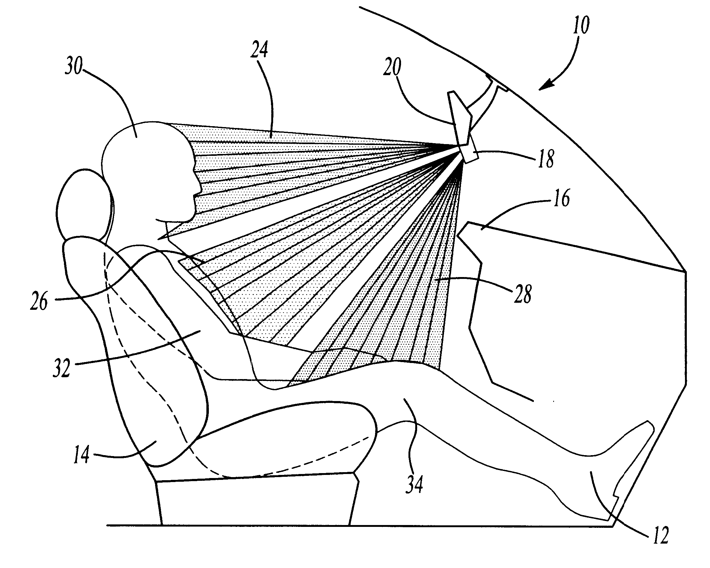
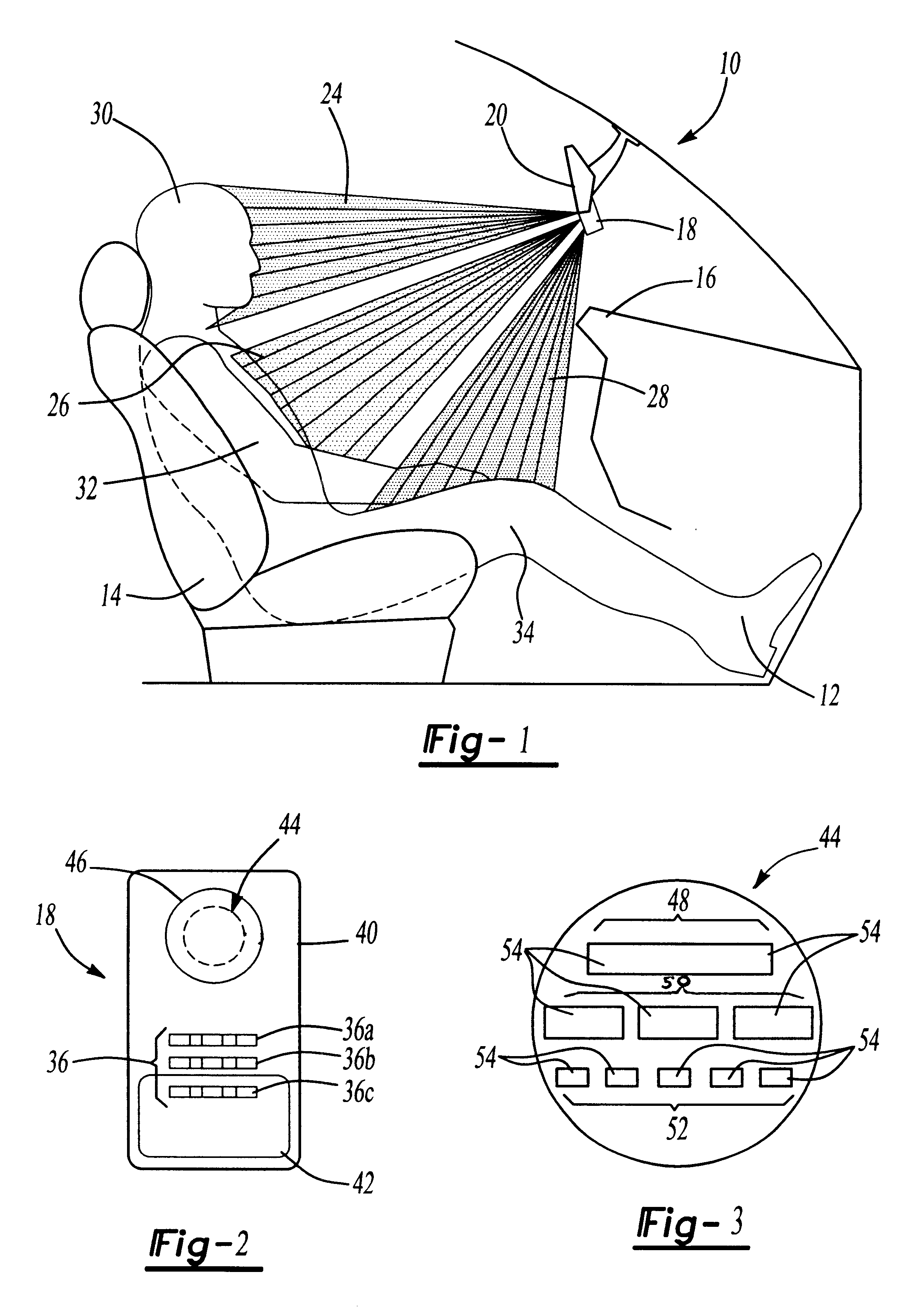
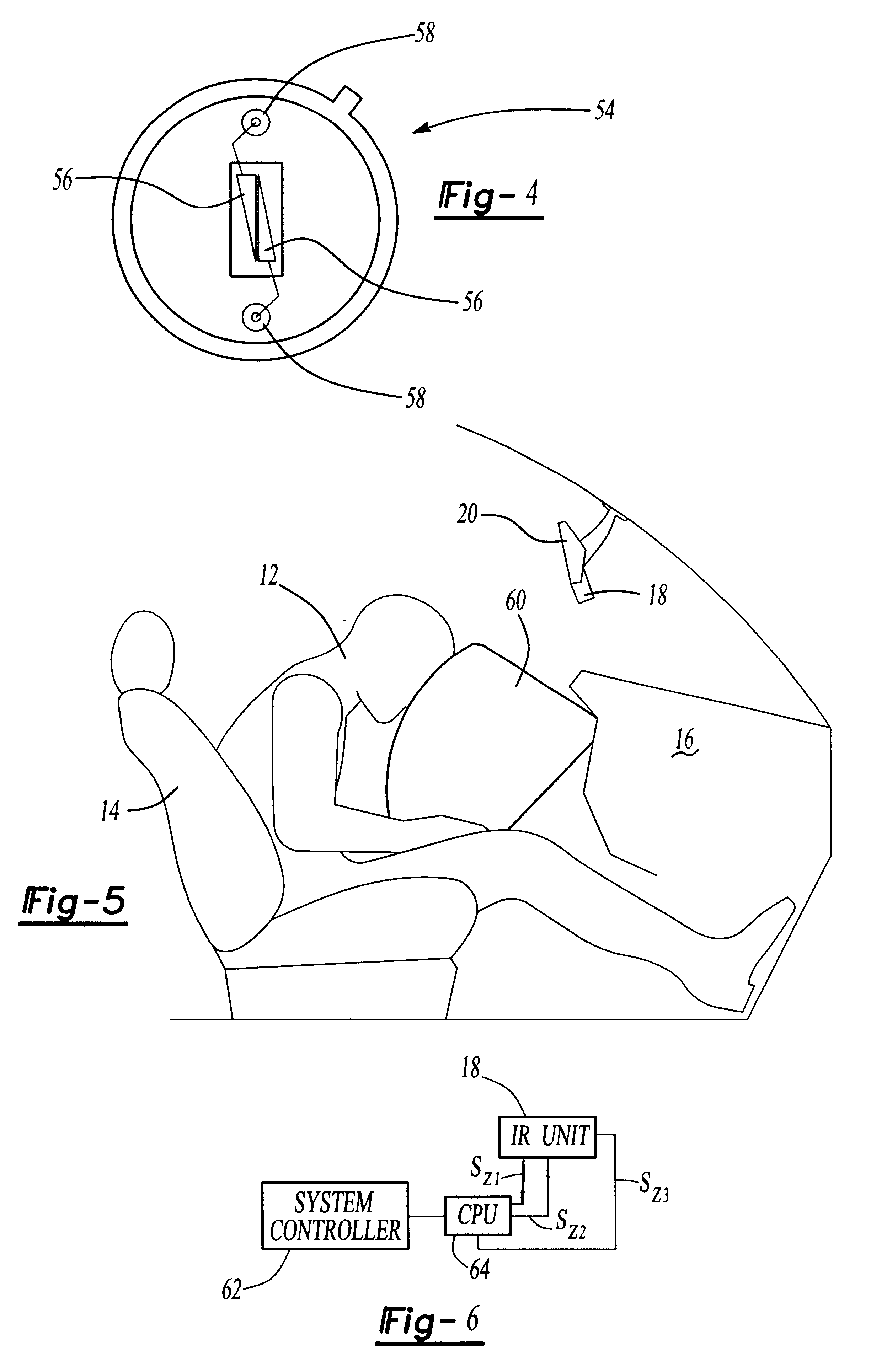
A vehicle is shown generally at 10 in FIG. 1. The vehicle 10 includes an occupant sensing system that continuously monitors the position of an occupant 12 within a vehicle 10 and provides occupant position information to control an airbag system based on position of the occupant 12 within the vehicle 10. Typically, the sensing system monitors the position of the occupant 12 when they are seated within the vehicle 10 on a vehicle seat 14. However, the system can also monitor the position of an occupant 12 located between the seat 14 and a vehicle dash 16, i.e., a child standing-up between the dash 16 and the seat 14.

The occupant sensing system includes a sensor unit 18 that is mounted to a vehicle structure. Preferably the sensor unit 18 is mounted at a relatively high vertical position within in the vehicle, such as by the rear-view mirror 20 as shown in FIG. 1. Instead of being centrally mounted, the unit 18 can be optionally mounted near the side of the vehicle 10 on an A-pillar, ...


PUM


Abstract

A vehicle occupant sensing system includes a laser array that generates three beams. A first beam is directed toward an upper body zone, a second beam is directed toward a middle body zone, and a third beam is directed toward a lower body zone. A first sensor assembly receives reflection beams from the upper body zone and generates a first signal that represents a proportional amount of an occupant present in the upper body zone. A second sensor assembly receives reflection beams from the middle body zone and generates a second signal that represents a proportional amount of the occupant present in the middle body zone. A third sensor assembly receives reflection beams from the lower body zone and generates a third signal that represents a proportional amount of the occupant present in the lower body zone. The laser array and the first, second, and third sensor assemblies are all mounted within a common housing that is mounted to a vehicle structure such as an A-pillar or rear view mirror. A central processor receives the first, second, and third signals and combines the signals to generate a control signal representative of the position of the occupant within the vehicle. The control signal is used to control deployment of an airbag based on the position of the occupant within the vehicle.

Description

1. Field of the InventionThis invention relates to a unique method and system for sensing position of an occupant within a vehicle where laser and sensor assemblies continuously monitor occupant position in three different zones.2. Related ArtMany vehicles have airbag systems that are used to restrain occupants within a vehicle under certain deceleration requirements. If the vehicle decelerates suddenly, such as when a collision occurs, occupants will tend to continue to move forward due to inertial effects. An airbag is deployed under these circumstances to decelerate the occupants' impact speed before they contact a vehicle structure, such as a steering wheel or dashboard. The deployment of the airbag decreases the likelihood of serious injury for the occupants.If vehicle occupants are positioned too close to the airbag, it may be desirable to decrease the deployment force of the airbag or to prohibit deployment of the airbag to prevent injury to the passenger from the impact of t...

Claims


Application Information

Patent Timeline
Patent Type & Authority Patents(United States)
IPC IPC(8): B60R21/01G01S17/00G01S17/88G01S17/02G01S17/87G01S7/48G01S7/481B60R1/12B60R21/015G01S17/04
CPCG01S7/4802G01S7/4811B60R21/01538G01S17/87G01S17/88B60R21/01534G01S17/026B60R2001/1223B60R2001/1253G01S17/04
Inventor COOK, JR., CHARLES R.O'ROURKE, DANCLARK, JEFFQUAIL, ALANNAWITT, PAULBRAUNWARTH, HUBERTCLARK, MARKREICH, DANPETERSON, LAUREN M.
Owner SIEMENS VDO AUTOMOTIVE CORP
Why Eureka
Try Eureka