
Double inlet arrangement for pulse tube refrigerator with vortex heat exchanger

a technology of vortex tube refrigerator and vortex tube, which is applied in the direction of refrigeration machines, hot gas positive displacement engine plants, gas cycle refrigeration machines, etc., can solve the problems that the refrigerator equipped with a blind vortex tube does not reach its maximum potential, and achieves the effect of superior heat-rejecting capacity, low cost and easy fabrication

Inactive Publication Date: 2002-09-03
MITCHELL MATTHEW P
View PDF7 Cites 26 Cited by
  • Summary
  • Abstract
  • Description
  • Claims
  • Application Information

AI Technical Summary

Benefits of technology

Accordingly, besides the objects and advantages of orifice pulse tube refrigerators in general and orifice pulse tube refrigerators equipped with vortex devices as warm heat exchangers, several objects and advantages of the present invention are:
(a) to provide a heat-rejecting heat exchanger with superior heat-rejecting capaci

Problems solved by technology

However, without ancillary arrangements for modifying the phase relationship between pressure and flow, and for exhausting hot fluid from its blind end, a refrigerator equipped with a blind vortex tube does not reach its maximum potential.

Method used


Image

  • Double inlet arrangement for pulse tube refrigerator with vortex heat exchanger
  • Double inlet arrangement for pulse tube refrigerator with vortex heat exchanger
  • Double inlet arrangement for pulse tube refrigerator with vortex heat exchanger

Examples


Embodiment Construction

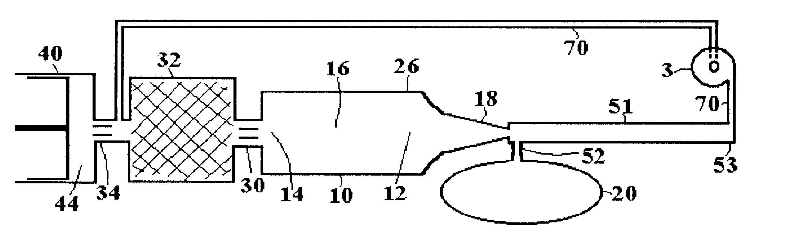
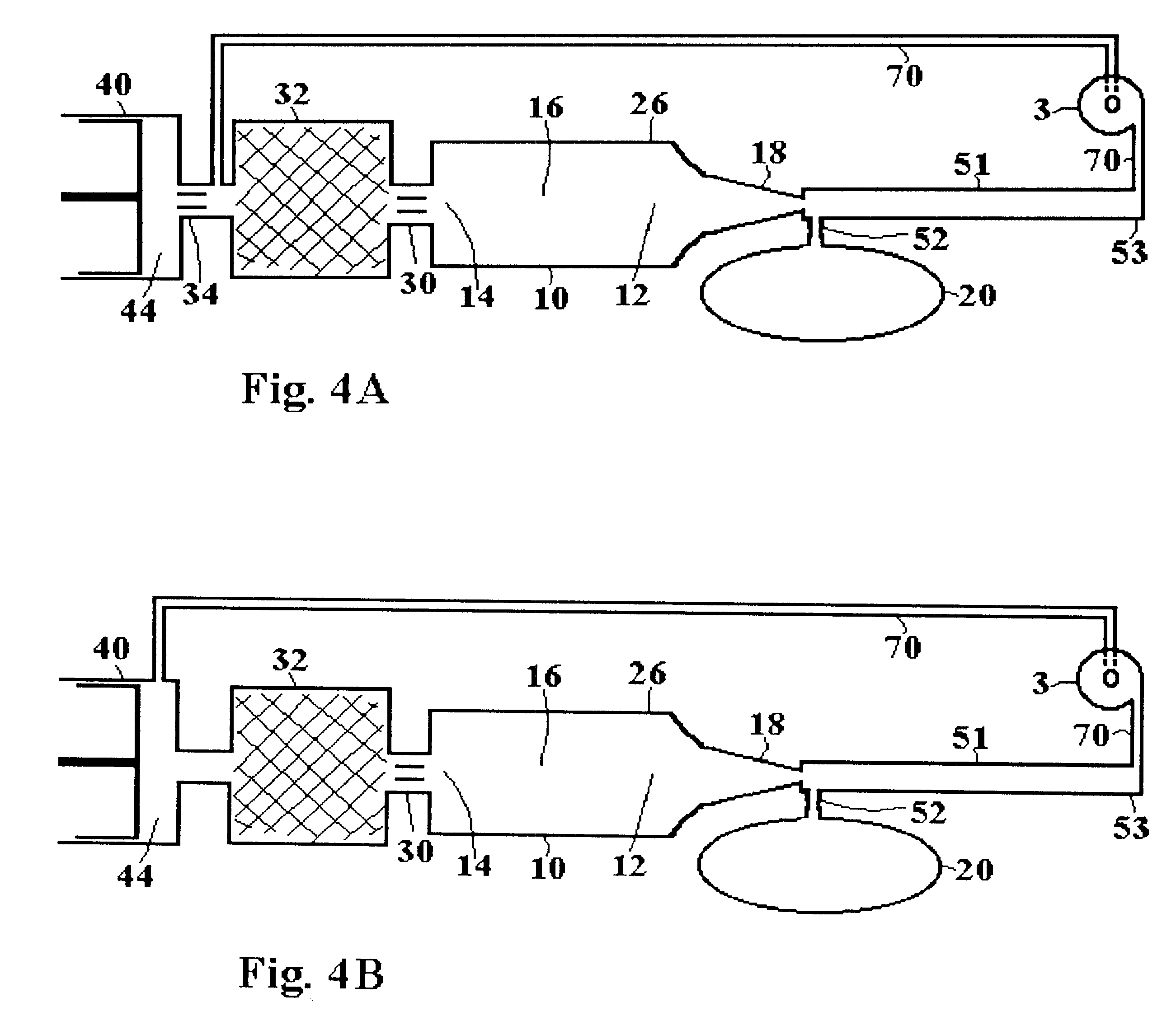
FIG. 4A is a schematic view of a preferred embodiment of a pulse tube refrigerator of this invention. It is similar to the pulse tube refrigerator of FIG. 2 except that remote end 53 of vortex tube 51 is connected to double inlet passage 70; diode 3 is interposed in double inlet passage 70; and the other end of double inlet passage 70 is connected between aftercooler 34 and regenerator 32.

FIG. 4B is a schematic view of an alternate preferred embodiment of a pulse tube refrigerator of this invention. It differs from the embodiment shown in FIG. 4A in that there is no aftercooler, and double inlet passage 70 is connected directly to compressor 40.

FIGS. 5A, 5B--PRIOR ART

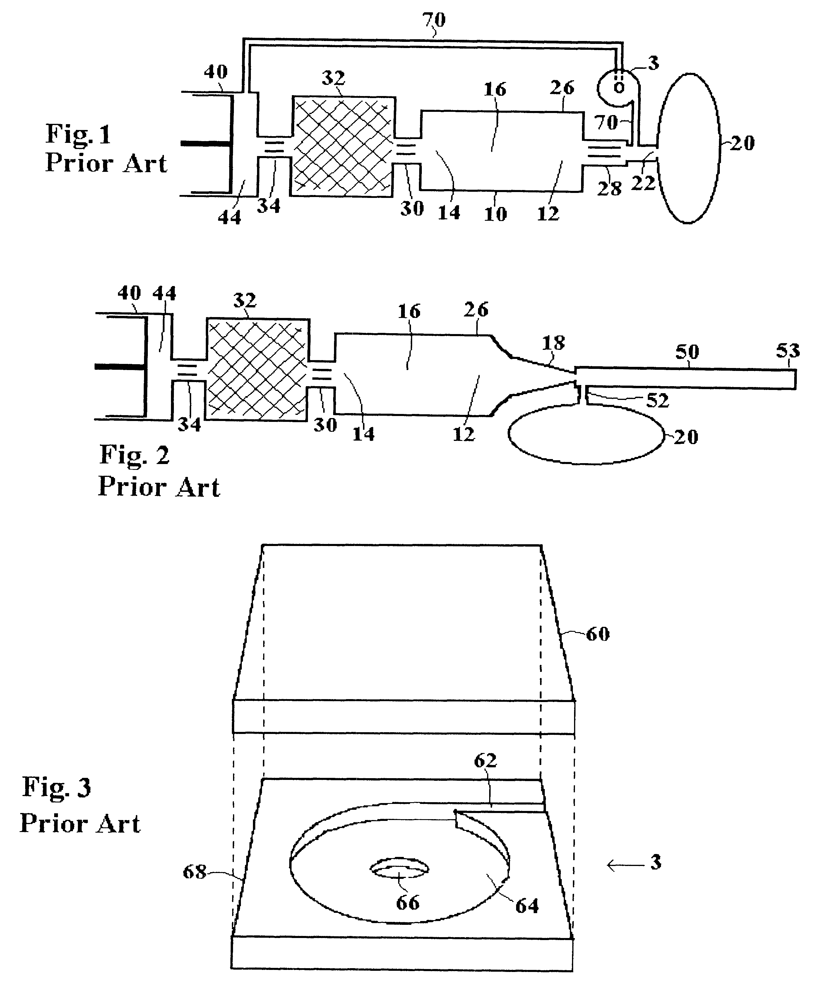
FIG. 5A is a schematic representation of flows in blind vortex tube 50 of FIG. 2 as fluid enters blind vortex tube 50 through cold throat 18 and exits blind vortex tube 50 through vortex generator 52. Vortex generator 52 comprises one or more passages that enter blind vortex tube 50 tangentially and immediately adjacent...


PUM


Abstract

A double inlet passage 70 connects a compressor 40 to remote end 53 of a vortex tube 51 that serves as the heat-rejecting heat exchanger of an orifice pulse tube refrigerator. Double inlet passage 70 includes means 3 for controlling DC flow in that passage. Fluid flows between compressor and reservoir enhance heat-rejecting effectiveness of vortex tube 51.

Description

1. Field of InventionThis invention relates to orifice pulse tube refrigerators and, in particular, to orifice pulse tube refrigerators that employ a vortex tube as the heat-rejecting heat exchanger at the warm end of the pulse tube.2. Description of Prior ArtIn the prior art double inlet arrangement for an orifice pulse tube refrigerator, a compressor is connected to the refrigerator in two places. One connection, through which flow is unrestricted, cyclically forces fluid into and withdraws fluid out of the regenerator, as shown in FIG. 1. The other connection, the "double inlet passage", is a restricted channel through which the compressor cyclically forces and withdraws a limited quantity of fluid. Heat exchangers and a pulse tube complete a loop between the two points at which the compressor is connected to the refrigerator.The double inlet passage is connected to the warm end of the prior art pulse tube between the warm heat exchanger and the orifice that connects the warm hea...

Claims


Application Information

Patent Timeline
IPC IPC(8): F25B9/02F25B9/04F25B9/14F25B9/00
CPCF25B9/04F25B9/145F25B9/00F25B2309/1407F25B2309/1411F25B2309/14241F25B2309/1427
Inventor MITCHELL, MATTHEW P.
Owner MITCHELL MATTHEW P
Learn More