

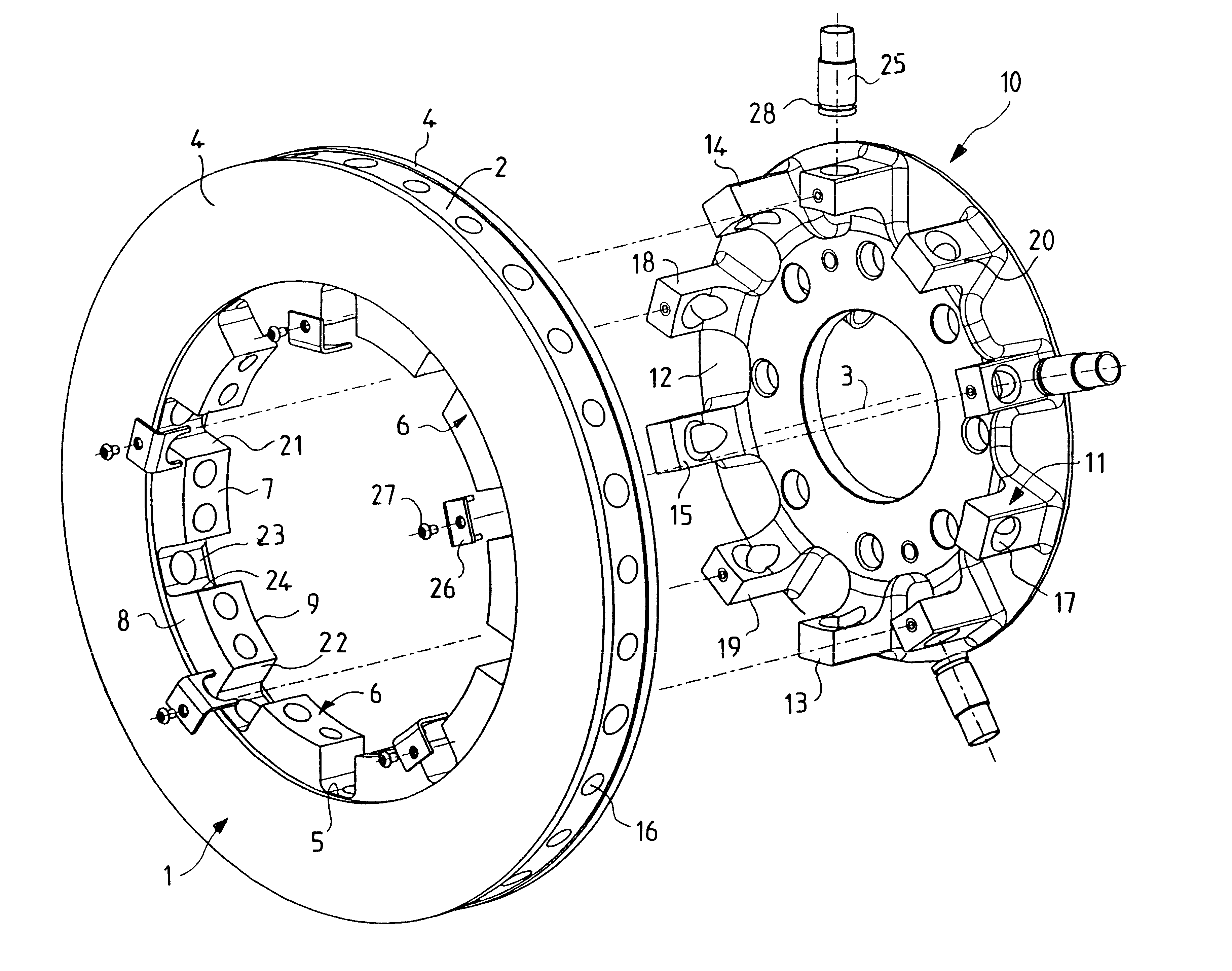
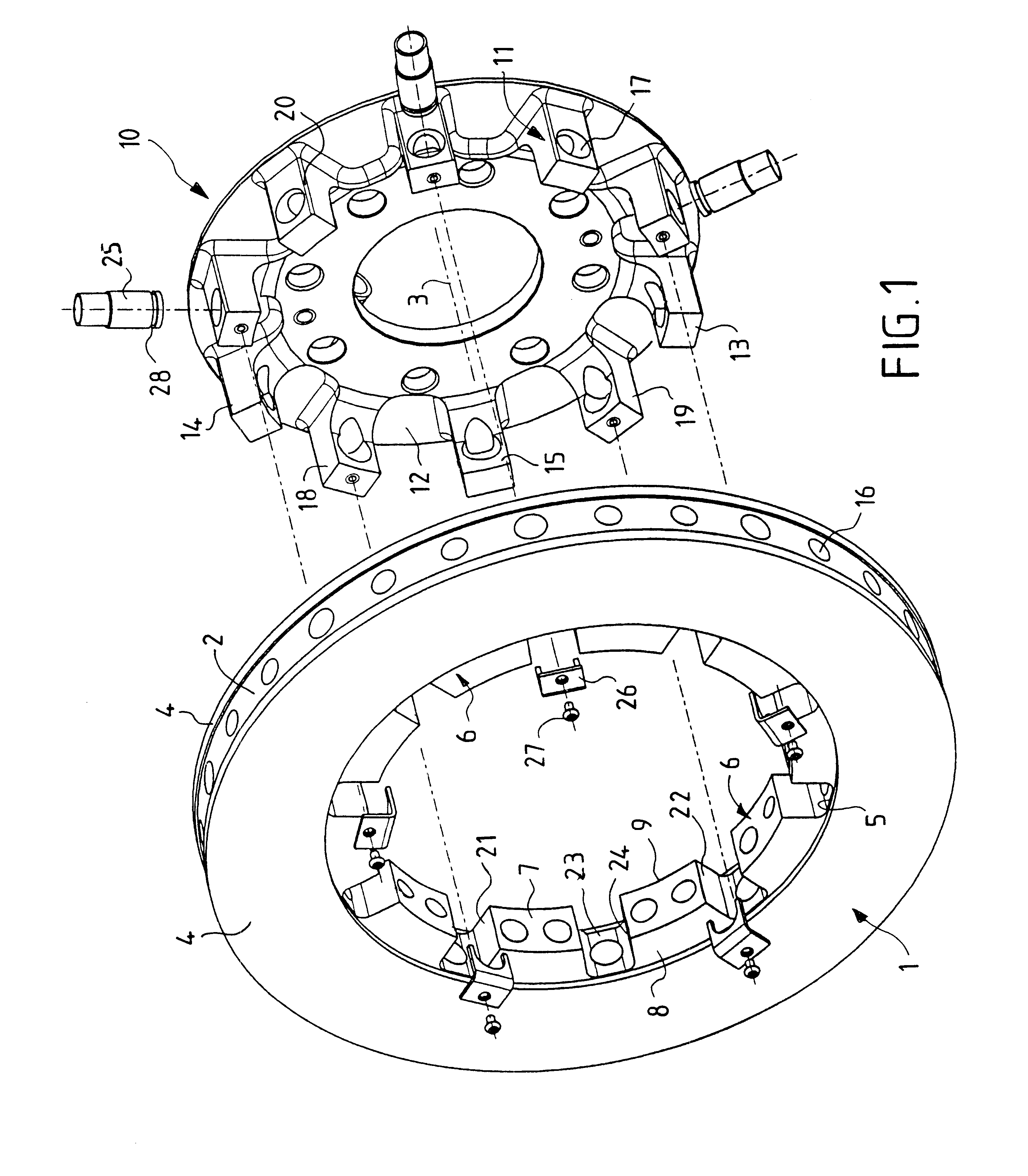
Device for fixing a ventilated brake disk axially on the hub of a motor vehicle wheel
a technology for ventilating brakes and wheels, which is applied in the direction of braking discs, braking systems, brake drums, etc., can solve the problems of affecting the service reducing the service life of the fixed mount, so as to achieve accurate control of the amount of play, reduce the effect of affecting the service life and the effect of reducing the number of times
- Summary
- Abstract
- Description
- Claims
- Application Information
AI Technical Summary
Benefits of technology
Problems solved by technology
Method used
Image

Examples
first embodiment
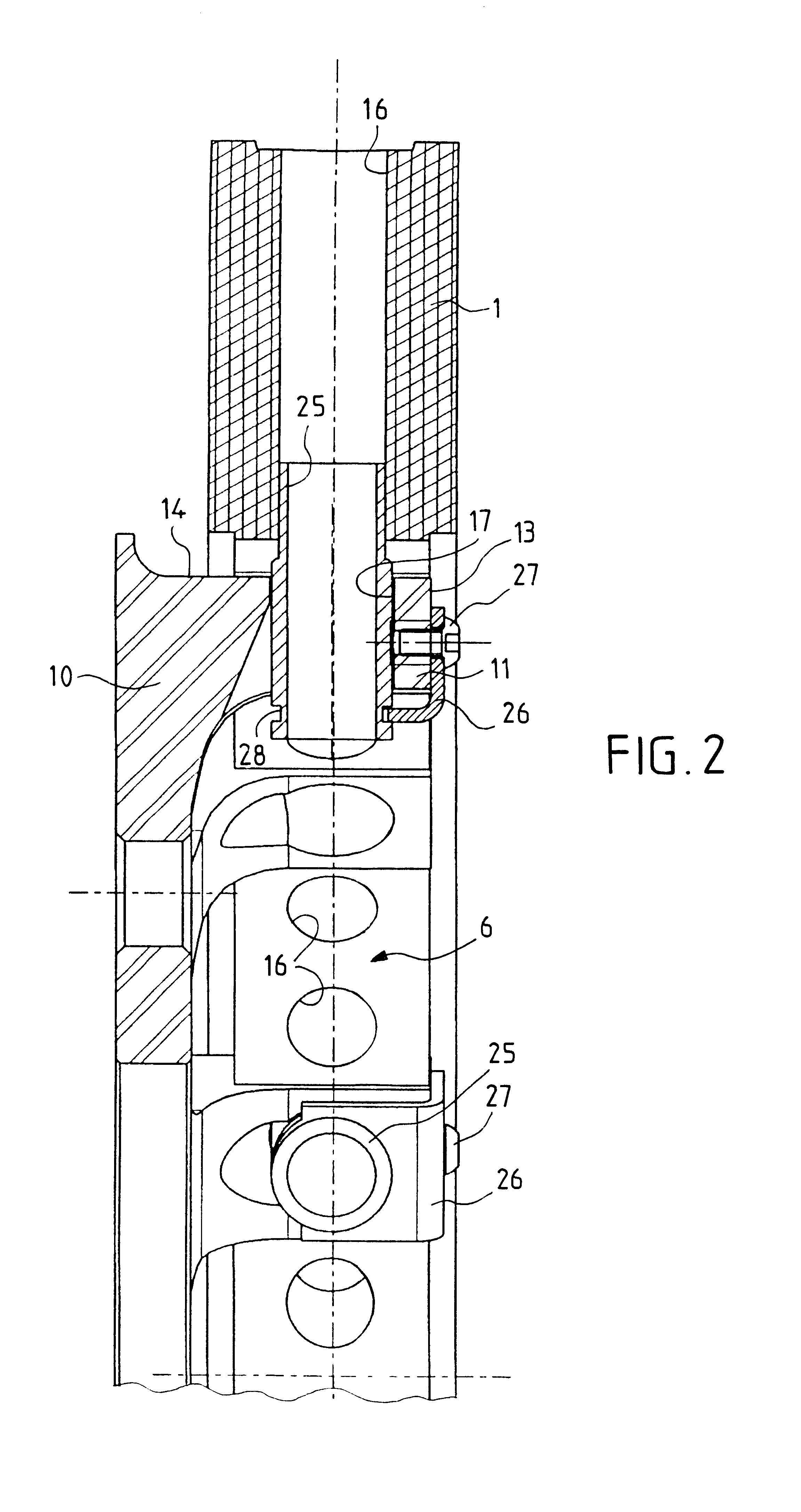
In a preferred first embodiment, and as shown in FIG. 2, the axial connection between the hub 10 and the annular disk 1 is provided by radial pegs 25, there being at least three such pegs that are angularly distributed, with each peg being engaged firstly with a small amount of play in the range 0.2 mm to 0.4 mm in a radial through channel 17 of a lug 11 and also with an exact fit in the radial ventilation duct 16 of the brake disk facing it. By passing in this way through both the hub and the disk, axial fixing is achieved with accurately controlled play. A stop plate 26 fixed (e.g. by means of a screw 27) in the distal face 13 of the lug co-operates with a groove 28 of the peg so as to keep it in position and prevent it from moving radially or being ejected under the effect of inertial forces, or more simply under the effect of vibration. Naturally, the invention is not limited to this particular solution and the stop plate 26 could be replaced by any other analogous locking means...
second embodiment
In a second embodiment, as shown in FIGS. 3 and 4, the axial connection between the hub 10 and the annular brake disk 1 can also be provided by at least three tabs 30 each fixed (e.g. by means of the screw 31) in the distal face 13 of a lug of the hub and having a free portion that co-operates with a slot 32 formed perpendicularly to the axis 3 in each of the two adjacent pieces 6 in relief of the inner peripheral edge 5 of the disk so as to hold the disk axially in order to avoid residual friction between the disk and the brake pads and so as to avoid problems of the pads lifting off the disk due to the disk moving at high speed. The lug 11 has a groove 33 that is likewise perpendicular to the axis 3 and located in line with the slot 32 in order to receive the free portion of the tab 30. This groove is slightly wider than the slot so as to provide a small amount of play of the order in the range 0.2 mm to 0.4 mm.
The materials used in the device of the invention (for making the pegs...
PUM
 Abstract
Description
Claims
Application Information