

Body structure for vehicle
a body structure and vehicle technology, applied in the direction of roofs, vehicle arrangements, transportation and packaging, etc., can solve the problem of not contributing to the absorption of impact energy
- Summary
- Abstract
- Description
- Claims
- Application Information
AI Technical Summary
Problems solved by technology
Method used
Image

Examples
second embodiment
FIG. 8 shows the second embodiment of the present invention. According to this embodiment, the reinforcement part 24 of the load-converting and transmitting member 21 is formed as a separate a reinforcement plate 24b which is connected to essentially the center of the rear face of the slanted or angled rib 22a, and arranged to extend back through the interior of the upper pillar 1B. The reinforcement plate 24b is secured in place by means of welding, bonding, etc.
Therefore, according to the second embodiment, it is possible to achieve essentially the same collision energy absorbing characteristics as the first embodiment. Additionally, owing to the provision of the reinforcement plate 24b which is separate (viz., not unitarily formed) from the upper pillar 1B, it is possible to achieve an increase in the freedom of design with respect to the front pillar 1 and the reinforcement part 24. Of course, by controlling both profile and thickness of flanges 24c and a bead 24d of the plate 2...
third embodiment
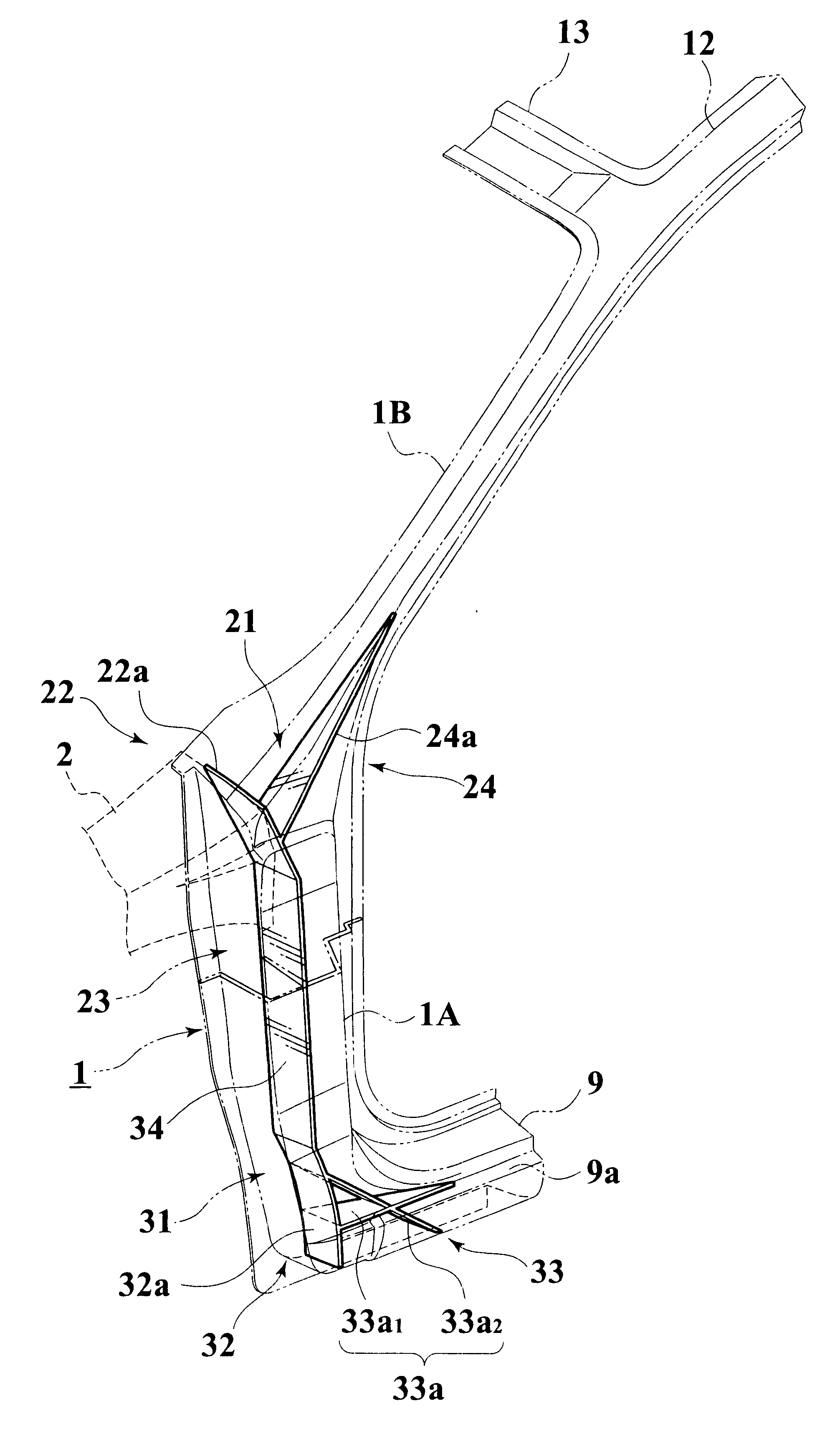
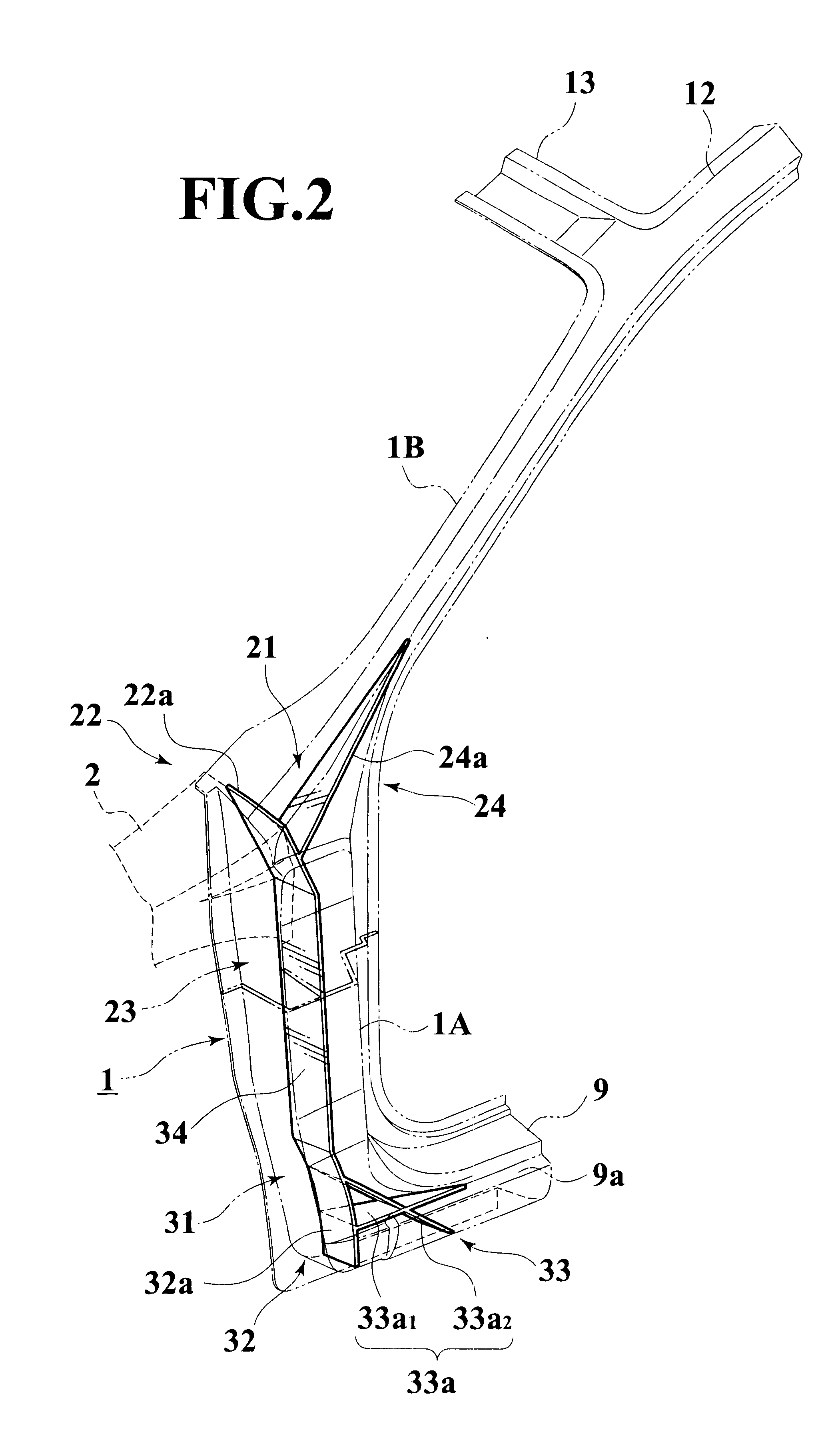
FIGS. 9 and 10 show a third embodiment of the invention. According to this embodiment, the angled rib 22a of the load-converting and transmitting member 21 is arranged so as to extend from a junction of the upper wall of the hood ridge member 2 and the front pillar 1 to the rear face or wall of the lower pillar 1A. A reinforcement part or portion 24 is defined by a thickened wall portion 24c which is either integrally formed on, or secured to, a portion of the rear wall of the lower pillar 1A to which the slanted rib 22a is integrated.
According to this embodiment of the invention, a reinforcement member 39 is additionally disposed in the lower pillar intermediate of the upper end which is connected to the hood ridge member 2 and the lower end which is connected to the side sill 9. The provision of the reinforcement member 39, renders it possible to provide both areas of the lower pillar portion which are faced by the slanted or angled rib 22a and the vertical rib 32a (shown by verti...
fourth embodiment
FIG. 11 shows a fourth embodiment of the invention. This arrangement, similar to the third embodiment, establishes a location of increased structural strength which automatically renders other portions relatively lower in resistance to structural deformation and thus achieves the same effect as the previously described embodiments. To increase the strength of the lower portion of the upper pillar portion 1B and / or an upper end portion of the hood ridge member 2, a reinforcement member or gusset 40 is welded or otherwise secured to an inboard edge of these two members in the manner shown in FIG. 11. This gusset 40 in this embodiment is located along and edge of the upper pillar 1B. In addition, another reinforcement member or gusset 41 is secured to an inboard edge of the lower pillar 1A.
The gusset 41 is attached to the upper part of the front pillar and gusset 41 is attached to the lower part of the front pillar. The gussets 40, 41 form more rigid portions, which have a relatively h...
PUM
 Abstract
Description
Claims
Application Information