Deformable antenna reflection surface

A reflective surface and reflective surface technology, applied in the direction of antennas, electrical components, etc., can solve the problems that the in-orbit reflector antenna cannot reduce the accuracy of the space antenna, the structure cannot be deformed, the space requirements of communication satellites, and the reflector antenna cannot meet complex and changeable problems. Achieve strong designability, high specific stiffness, and overcome low surface accuracy

Active Publication Date: 2010-10-27
HARBIN INST OF TECH
View PDF2 Cites 20 Cited by
  • Summary
  • Abstract
  • Description
  • Claims
  • Application Information

AI Technical Summary

Problems solved by technology

[0007] The purpose of the present invention is to solve the problem that the current reflector antenna cannot meet the complex and changeable space environment, and the on-orbit thermal deformation control and on-orbit vibration control cannot be performed on i...

Method used


Image

  • Deformable antenna reflection surface
  • Deformable antenna reflection surface
  • Deformable antenna reflection surface

Examples


specific Embodiment approach 1

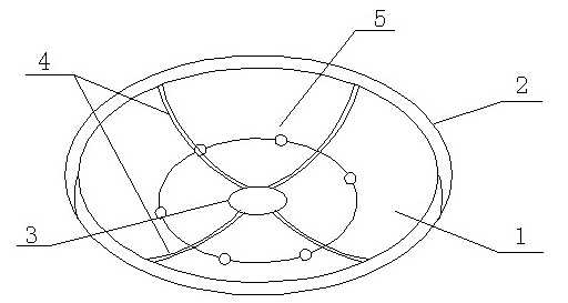
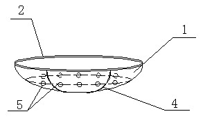
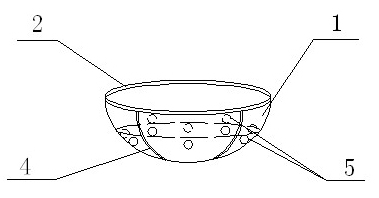
[0013] Specific implementation mode one: combine figure 1 Describe this embodiment, the deformable antenna reflecting surface of this embodiment includes a reflective surface body 1, a first hoop stiffener 2, a second hoop stiffener 3 and a set of radial stiffeners 4, with the reflective surface body 1 in the middle A parabolic surface with a circular opening is provided, a first hoop reinforcement 2 is fixedly connected to the upper edge of the back of the reflective surface body 1, and a second hoop reinforcement is fixedly connected to the lower edge of the back of the reflective surface body 1. Part 3, the back of the reflective surface body 1 between the first hoop reinforcement 2 and the second hoop reinforcement 3 is provided with a group of radial reinforcement pieces 4 arranged along the parabolic direction, and the deformable antenna reflection surface is also Including a group of drivers 5, the driver 5 includes an end cover 5-1, a drive shaft 5-2, a housing 5-3, a ...

specific Embodiment approach 2

[0017] Embodiment 2: The driver 5 of this embodiment also includes a resistance heating film 5-6, and the outside of the driving functional material body 5-5 is provided with a resistance heating film 5-6, wherein the positive and negative electrodes of the wire 5-4 and the resistance heating Membranes 5-6 are connected. The resistance heating film 5-6 is made of nickel-chromium resistance material, nickel-chromium-iron resistance material, iron-chromium resistance material, nickel-chromium-aluminum-iron resistance material, iron-chromium-aluminum resistance material, molybdenum resistance material, pure nickel resistance material, manganese-copper resistance material, Made of constantan resistance material, copper nickel resistance material, iron resistance material or copper resistance material. Other components and connections are the same as those in the first embodiment.

specific Embodiment approach 3

[0018] Specific Embodiment Three: The piezoelectric material of this embodiment is composed of 5 to 98 parts of dielectric elastomer material and 2 to 95 parts of reinforcing phase material according to the volume fraction ratio. The piezoelectric material has simple structure, direct drive, low cost and light weight , large displacement and high efficiency, it is currently a driving material with important potential application value. Other components and connections are the same as those in the first embodiment.


PUM

PropertyMeasurementUnit
Thicknessaaaaaaaaaa

Abstract

The invention discloses a deformable antenna reflection surface and relates to the antenna reflection surface. The invention aims at solving the problems that the existing reflector antenna can not meet the space environment which is complex and variable and can not carry out orbit thermal deformation control and on-orbit vibration control in space, thereby reducing the precision of the on-orbit reflector antenna and being incapable of meeting various space requirements because the existing space antenna can not have the structural deformation. A driver comprises an end cover, a driving shaft, a housing, a working coil or a conducting wire and a driving functional material body, wherein the end cover is arranged on the housing, the driving shaft is crisscross, one end of the driving shaftis connected with the end cover, the opposite end is connected with the driving functional material body, the other two ends are in contact with the side wall of the housing, the driving shaft can slide along the axial direction of the housing, and the working coil or the conducting wire is arranged between the driving shaft and the housing and positioned outside the driving functional material body. The antenna reflection surface is used for realizing the control of the orbit thermal deformation, the vibration control and the reflection surface deformation of a space-vehicle antenna.

Description

technical field [0001] The invention relates to an antenna reflection surface. Background technique [0002] In the future, satellite communications, space exploration, ground tracking and radio astronomy will all widely use large-aperture reflector antennas. Although the previous mesh antennas were adjusted on the ground to meet the requirements of mesh accuracy (previous studies were limited to ground adjustments), Since the space environment is a complex and changeable environment, on-orbit thermal deformation control and on-orbit vibration control cannot be performed on it, so the on-orbit antenna still has an unexpected drop in accuracy. [0003] For communication satellites, communication satellites, the earth, the moon and the sun are constantly running in their respective orbits day and night, when they are in a specific relative position, it will affect the satellite communication and reduce the quality of communication; With the trends of miniaturization of broadb...

Claims


Application Information

Patent Timeline
IPC IPC(8): H01Q15/16
Inventor 冷劲松刘彦菊张蕊瑞兰鑫
Owner HARBIN INST OF TECH
Why Eureka
Try Eureka