
Method, system, and program for monitoring a device with a computer using user selected monitoring settings

a monitoring system and computer technology, applied in the direction of digital output to print units, instruments, nuclear elements, etc., can solve the problems of not being able to provide detailed error status information back to the client application, not being able to guarantee that a transmission was received, and many of the current printer monitoring systems are not flexibl

Inactive Publication Date: 2002-09-17
RICOH KK
View PDF26 Cites 102 Cited by
  • Summary
  • Abstract
  • Description
  • Claims
  • Application Information

AI Technical Summary

Benefits of technology

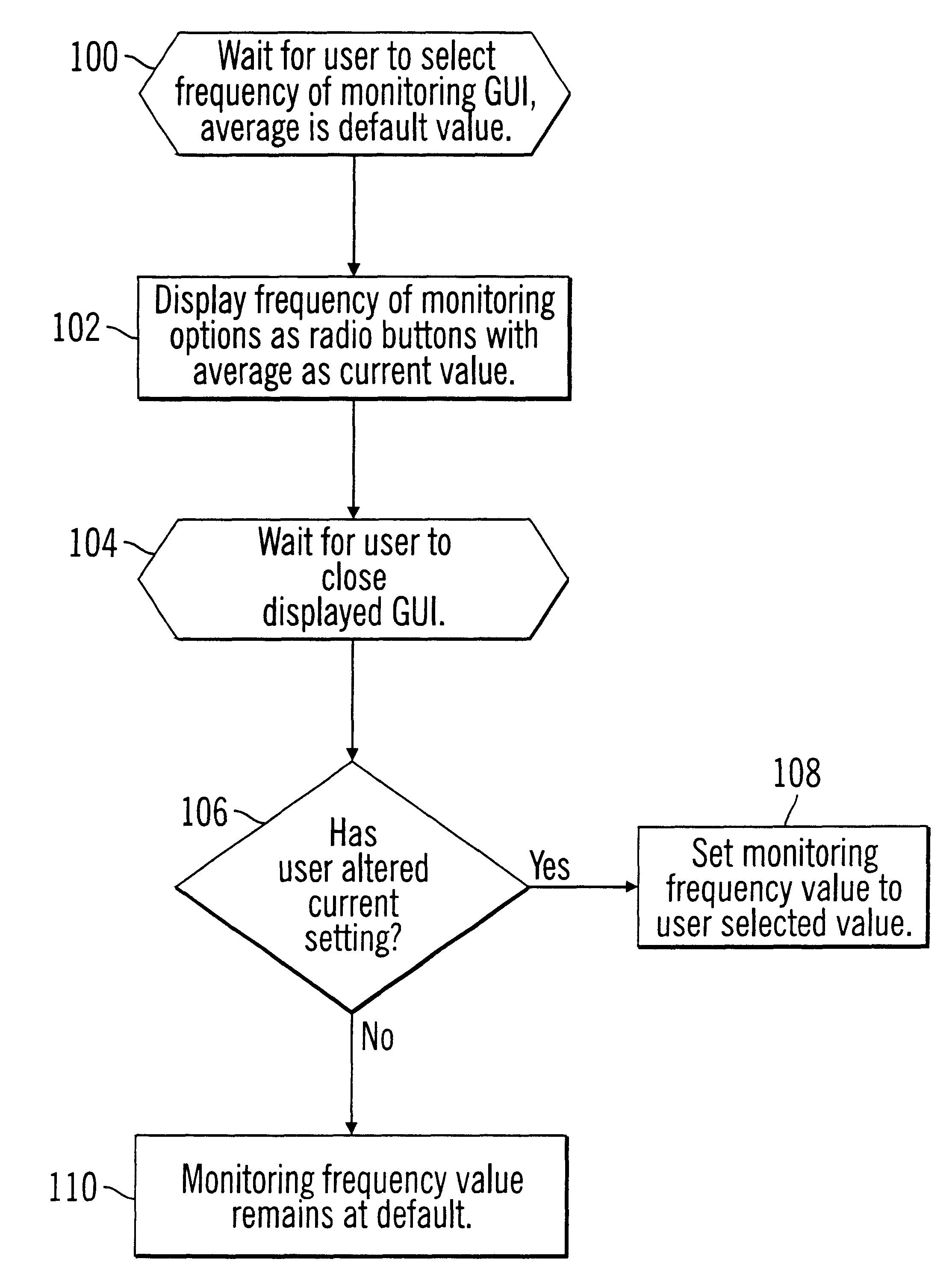
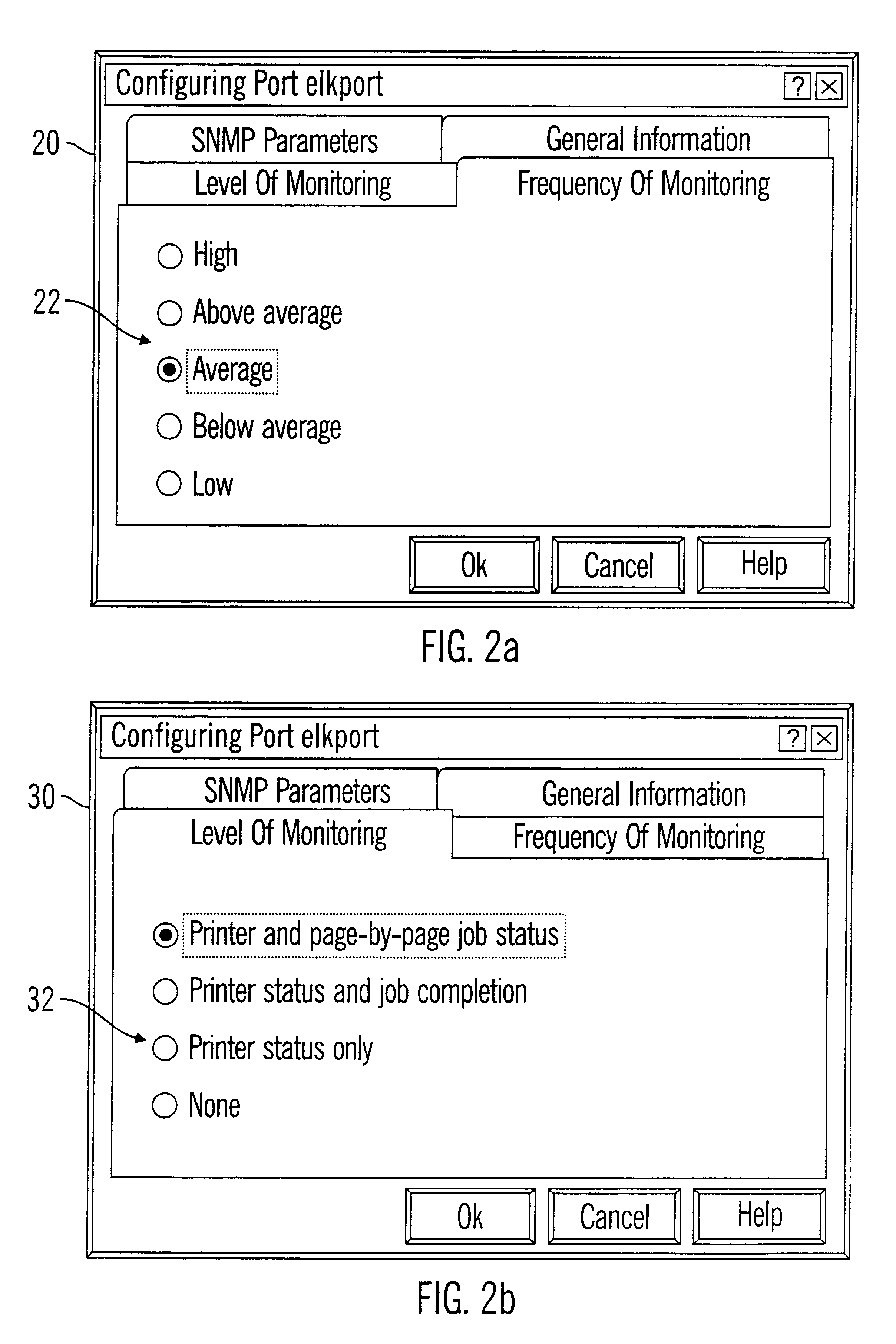
Preferred embodiments allow a user to select a monitoring frequency value. This user selected monitoring frequency value is then used to determine a polling interval between a computer and a network device, such as a printer. If there are numerous different polling interval types for various types of operational states, e.g., an active print job at the printer, no print job sent, no traps received when there is a print job, no traps received when there is no print job, then the user selected monitoring frequency value may be used to determine the corresponding polling interval to use. In this way, the user selects a readily understandable monitoring frequency value that corresponds to a user goal to lower network traffic or increase the timeliness of status information. This user selected value is then used to determine specific settings for polling operations that would otherwise be difficult to explain to the user.
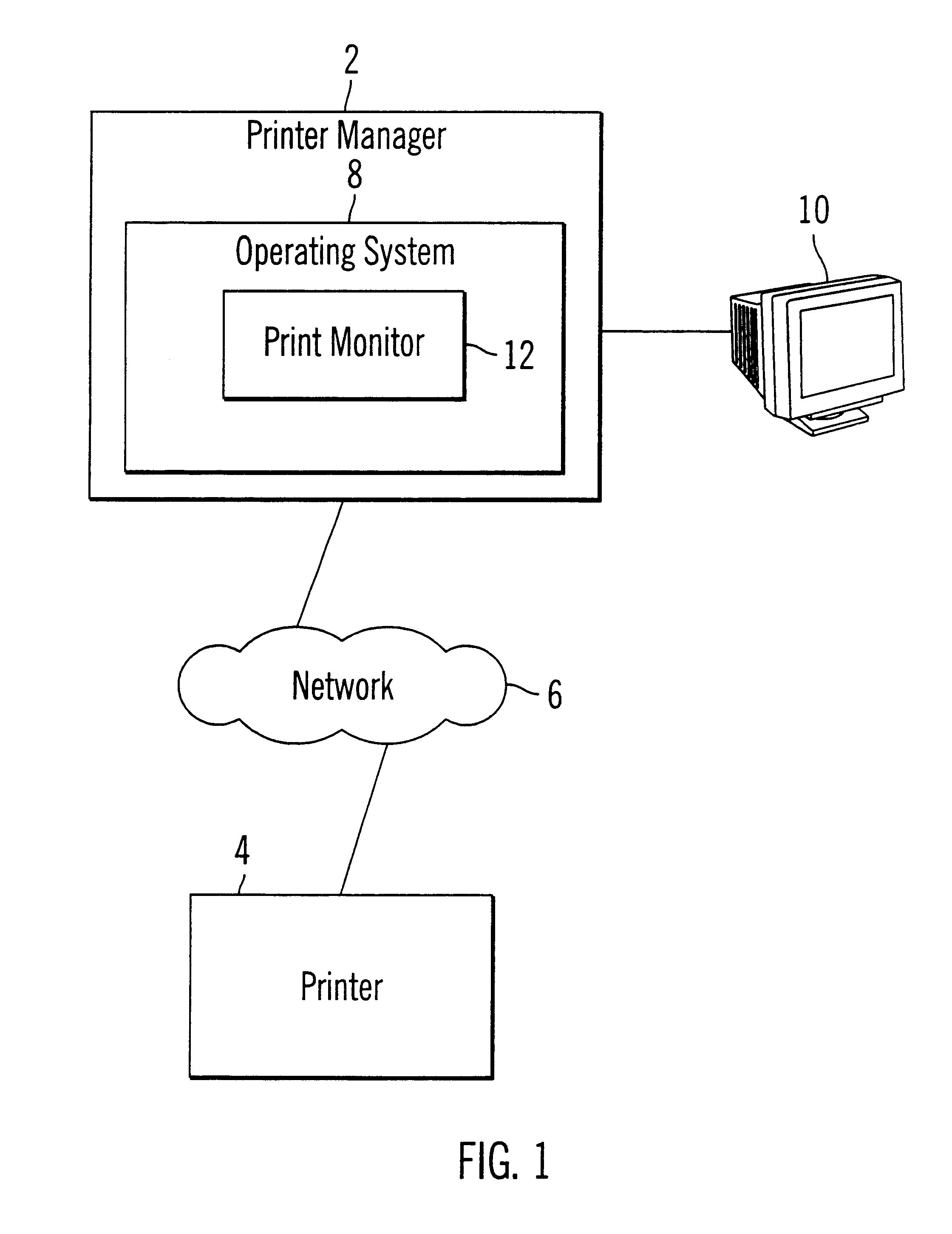
Preferred embodiments thus provide a mechanism to allow a user at a high level to select a primary monitoring goal, i.e., increased monitoring frequency to improve timeliness of status information versus decreasing network traffic. From the high level value the user selects, the print monitor 12 would then calculate the appropriate specific polling values to use to accomplish the monitoring goal the user has selected.

Problems solved by technology

However, LPR is not capable of providing detailed error status information back to the client application.
Thus, one may fail, and the other would carry on.
As a result, with SNMP, there is no guarantee that a transmission was received.
Although most messages do transmit successfully, those that do not cannot be retransmitted.
However, many of the current printer monitoring systems are not flexible and do not provide a wide range of settings that may be tailored to a users goals and system needs.

Method used


Image

  • Method, system, and program for monitoring a device with a computer using user selected monitoring settings
  • Method, system, and program for monitoring a device with a computer using user selected monitoring settings
  • Method, system, and program for monitoring a device with a computer using user selected monitoring settings

Examples


Embodiment Construction

To overcome the limitations in the prior art described above, preferred embodiments disclose a method, system, and program for determining monitoring settings for a computer monitoring a device. A set of monitoring frequency values is provided for a user to select. A user selected monitoring frequency value is received and used to determine at least one polling interval that defines a period between polling operations from the computer to the device. The polling interval value is a different value from the user selected monitoring frequency.

In further embodiments, a base polling interval is determined that corresponds to a base monitoring frequency value in the set. A separate polling interval is then determined for each monitoring frequency value in the set, other than the base monitoring frequency. The polling interval corresponding to the selected monitoring frequency value is used to determine the period between polling operations.

In still further embodiments, there are multiple...


PUM


Abstract

Disclosed is a method, system, and program for determining monitoring settings for a computer monitoring a device. A set of monitoring frequency values is provided for a user to select. A user selected monitoring frequency value is received and used to determine at least one polling interval that defines a period between polling operations from the computer to the agent device. The polling interval value is a different value from the user selected monitoring frequency.

Description

1. Field of the InventionThe present invention relates to a method, system, and program for monitoring a device with a computer using a user selected setting and, in particular, monitoring printers in a network.2. Description of the Related ArtNetwork printing systems generally comprise an assemblage of different printers, client computers, servers, and other components connected over a network. A network administrator or user may want to monitor the status of print jobs being printed or the general operational status of the printer. A computer may monitor a remote printer over a network using a network protocol, such as SNMP or TCP / IP, or a line connection such as a parallel port connection. Current printer software includes a print monitor component to monitor printer operations. For instance in the Microsoft Windows 95 / 98 systems, the user may display a queue of print jobs for the printer and a current status of the print jobs. The status usually indicates whether a particular qu...

Claims


Application Information

Patent Timeline
IPC IPC(8): G06F3/12
CPCG06F3/121G06F3/1229G06F3/1259G06F3/1285G06F3/1204G06F3/05
Inventor CARNEY, DENNIS MICHAELLIEBELT, LINDA SUENGUYEN, RYAN HOA
Owner RICOH KK
Learn More