Dispensing device

Inactive Publication Date: 2002-10-01
BATTELLE MEMORIAL INST
View PDF104 Cites 87 Cited by
  • Summary
  • Abstract
  • Description
  • Claims
  • Application Information

AI Technical Summary

Problems solved by technology

One problem associated with inhalers it coordinating the

Method used


Image

  • Dispensing device
  • Dispensing device
  • Dispensing device

Examples


Embodiment Construction

In FIGS. 1 and 2, a device of the invention is illustrated in which a pressure reduction created by the action of breathing through a suitable ducting (1) causes a lightweight flap (2), balanced by a second member (3) pivoted at a hinge (4) and connected to a dc high voltage supply of either polarity (5) to revolve through a sufficient degree of arc to allow the second member of the flap to become exposed to the electric field and then create gaseous ions.

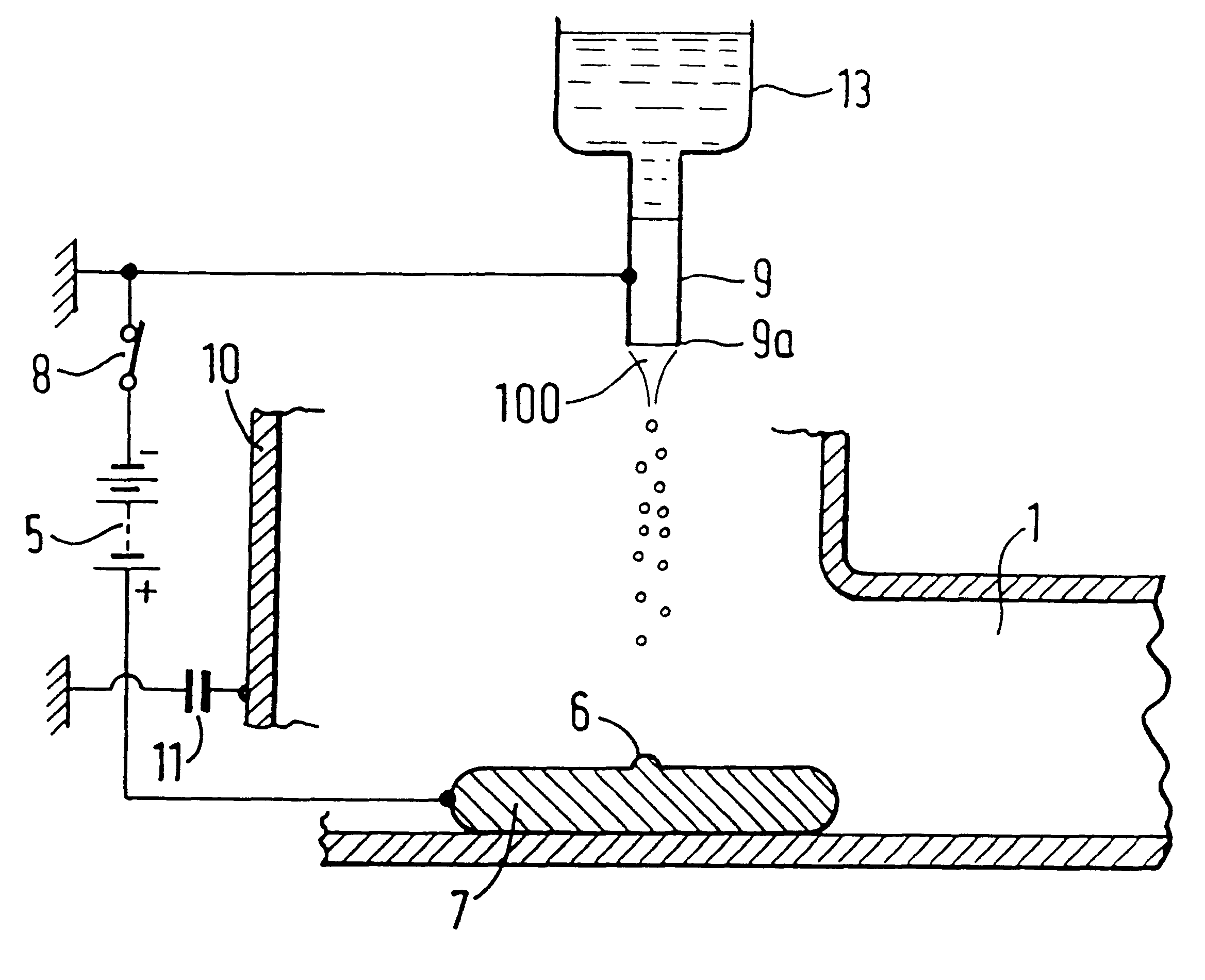
The flap valve thus has two actions: (a) it opens an air passage (1) to facilitate a flow of droplets; and (b) is simultaneously rotates a balancing member (3) attached to the flap (2) through a sufficient degree of arc to expose a ridge, or nipple (6) having one dimension of less than about 1.0 mm radius of curvature.

The ridge, or nipple (6) may be made of any conducting, or semi-conducting material such as metal, or carbon-loaded plastic, and is connected to a source of high voltage (5). When not actuated by breathing, the ridge ...


PUM


Abstract

An inhaler for enabling inhaled administration, has a housing having an outlet duct defining a passageway through which air can be drawn by inhalation on the part of a user. The housing contains a capillary nozzle; a container for containing a quantity of liquid to be supplied to the capillary nozzle; and an electric field controller for applying a voltage to the liquid prior to issue from the container via the capillary nozzle to expose the liquid to an electric field to cause comminution of the liquid emerging from the capillary nozzle to product a spray of electrically charged droplets such that upon inhalation by the user, electrically charged droplets for the deposition in the user's airways.

Description

The invention relates to a dispensing device for comminuting a liquid and the uses of such a device, especially in medicine.1. BackgroundDispensing devices are known which produce a finely divided spray of liquid droplets by electrostatic (more properly referred to as `electrohydrodynamic`) means. The droplet spray in such devices is generated by the application of an electric field to a liquid at a spray head or spray edge. The potential of the applied electric field is sufficiently high to provide comminution of the liquid from the spray head. The droplets produced are electrically charged and thus are prevented from coagulating by mutual repulsion.Electrohydrodynamic sprayers have potential uses in many areas, including agriculture and the automotive industry and also for dispensing cosmetics and medicines.2. Prior ArtUnited Kingdom patent number 1569707 describes such an electrohydrodynamic spray device principally for use in crop spraying.United Kingdom patent number 2018627B d...

Claims


Application Information

Patent Timeline
IPC IPC(8): A61M15/00A61M15/02B05B5/025B05B5/043B05B5/00
CPCA61M15/0091A61M15/02B05B5/002B05B5/0255B05B5/043A61M15/0093
Inventor COFFEE, RONALD ALAN
Owner BATTELLE MEMORIAL INST
Why Eureka
Try Eureka