Foreign particle resistant valve

a technology of foreign particle and valve body, applied in the direction of valve details, valve arrangement, valve operating means/release devices, etc., can solve the problems of inability to open or close the main valve position, the most susceptible to foreign particle blockage, and the failure to facilitate the fabrication and service cleaning of the main valve, and achieve precise dimensional tolerance control.

Inactive Publication Date: 2002-10-01
KOLZE
View PDF13 Cites 39 Cited by
  • Summary
  • Abstract
  • Description
  • Claims
  • Application Information

AI Technical Summary

Benefits of technology

The present invention focuses primarily on two basic methods to prevent foreign particle orifice passage blockage of a pilot operated valve that controls differential pressures across a pressure sensitive member such as a diaphragm having a poppet seat to open and close a main flow port of the valve. As is well understood by those knowledgeable in the state of the art of these valves, a blockage of the upstream orifice or bleed orifice of this pilot flow passage will cause a failure to close condition of the main valve port and could thereby lead to flooding and property damage. On the other hand, a blockage of the downstream or pilot actuator orifice results in a failure to open or a closed main valve position, and although not desirable, is not usually as serious as with a blockage of the upstream orifice. Agrevating the possible failure to close problem is that the upstream orifice is, by diaphragm operation necessity, made smaller than the downstream pilot actuator orifice and is therefore the most susceptible to foreign particle blockage. To overcome this major problem, one method utilized in the present invention provides a screening means which will only permit passage of particles small enough to harmlessly pass through the upstream pilot orifice and another method provides a means whereby this upstream orifice has been enlarged so that it no longer is the minimum pilot passage area and therefore becomes less prone to the foreign particle blockage condition. In the screening method, an arrangement of small screening passages are formed between the periphery of the diaphragm seal and the valve body while another screen version utilizes a removable plastic screening member to facilitate its fabrication and service cleaning and can also be adapted to either a plastic or metal body. In the latter version, the screen passages are formed between the valve body and the removable member which is sandwiched between the outer peripheral seal of the diaphragm and valve body. In still another version, the screening passages are formed in the central portion of the flexible diaphragm. In all versions the means whereby the screen passages are formed permit a very precise dimensional tolerance control and thereby assure proper foreign particle screening of the pilot flow orifice passages.
A second approach toward minimizing pilot valve foreign particle orifice blockage utilizes a series connected enlarged orifice passages which together produce an equivalent pressure drop of a single small orifice. By this arrangement, a larger bleed hole passage can be used which results in a much larger orifice passage area and thereby makes this passage much less likely to become blocked and also permits the use of less critical and larger size screen passages. In addition, the series orifice passage diameters can tolerate considerably more tolerance variability than that allowed for a single bleed orifice and thereby also improves the dimensional control of the pilot valve bleed orifice. In the series orifice passage embodiment, three versions are illustrated, one provides the passages in the peripheral rim of the diaphragm, a second version provides these series passages in a separate elastomeric ring, and a third version illustrates the series connected passages in the central portion of the diaphragm. In the second and third versions, the series bleed passages can be placed downstream of the screening passages to add an extra protective margin against possible foreign particle blockage of the bleed passage. The series orifice bleed passages provide the simplest means to attain the larger bleed passages, but a further enlargement of these passages may be achieved by the addition of a vortex flow means with each series orifice. Vortex flow restrictors add an extra pressure drop to a simple orifice and are well known configurations by persons familiar in the state of the art of fluid flow and are therefore not more fully explained or illustrated but are mentioned as an option to add extra pressure drop to the series orifice passages if needed in an application of the invention.
In some applications, foreign particle protection may not be a critical condition and in these cases the series connected pressure drop passages could be dimensionally the same as that used in a single orifice but would result in a greater pressure differential across the pressure responsive main valve member. This would permit use of a smaller diameter pilot valve seat and thereby reduce the required actuation lift force which in turn would permit the use of a more economical pilot valve actuator. The improved series connected passages so sized and combined with the improved screening means described previously would provide additional benefit of the described invention.
Therefore, the present invention as described, has thus achieved its objectives of improving a pilot operated valve assembly for improved resistance against foreign particle bleed passage blockage by: (1) an improved pilot screening means, (2) an enlarged bleed orifice passage less susceptible to foreign particle blockage, (3) provision to permit removal of foreign particle screen means for service cleaning, (4) providing an improved dimensional control of the pilot bleed passage, and (5) the capability to incorporate the foreign particle protection improvements into either plastic or metal valve bodies.

Problems solved by technology

As is well understood by those knowledgeable in the state of the art of these valves, a blockage of the upstream orifice or bleed orifice of this pilot flow passage will cause a failure to close condition of the main valve port and could thereby lead to flooding and property damage.
On the other hand, a blockage of the downstream or pilot actuator orifice results in a failure to open or a closed main valve position, and although not desirable, is not usually as serious as with a blockage of the upstream orifice.
Agrevating the possible failure to close problem is that the upstream orifice is, by diaphragm operation necessity, made smaller than the downstream pilot actuator orifice and is therefore the most susceptible to foreign particle blockage.

Method used


Image

  • Foreign particle resistant valve
  • Foreign particle resistant valve
  • Foreign particle resistant valve

Examples


Embodiment Construction

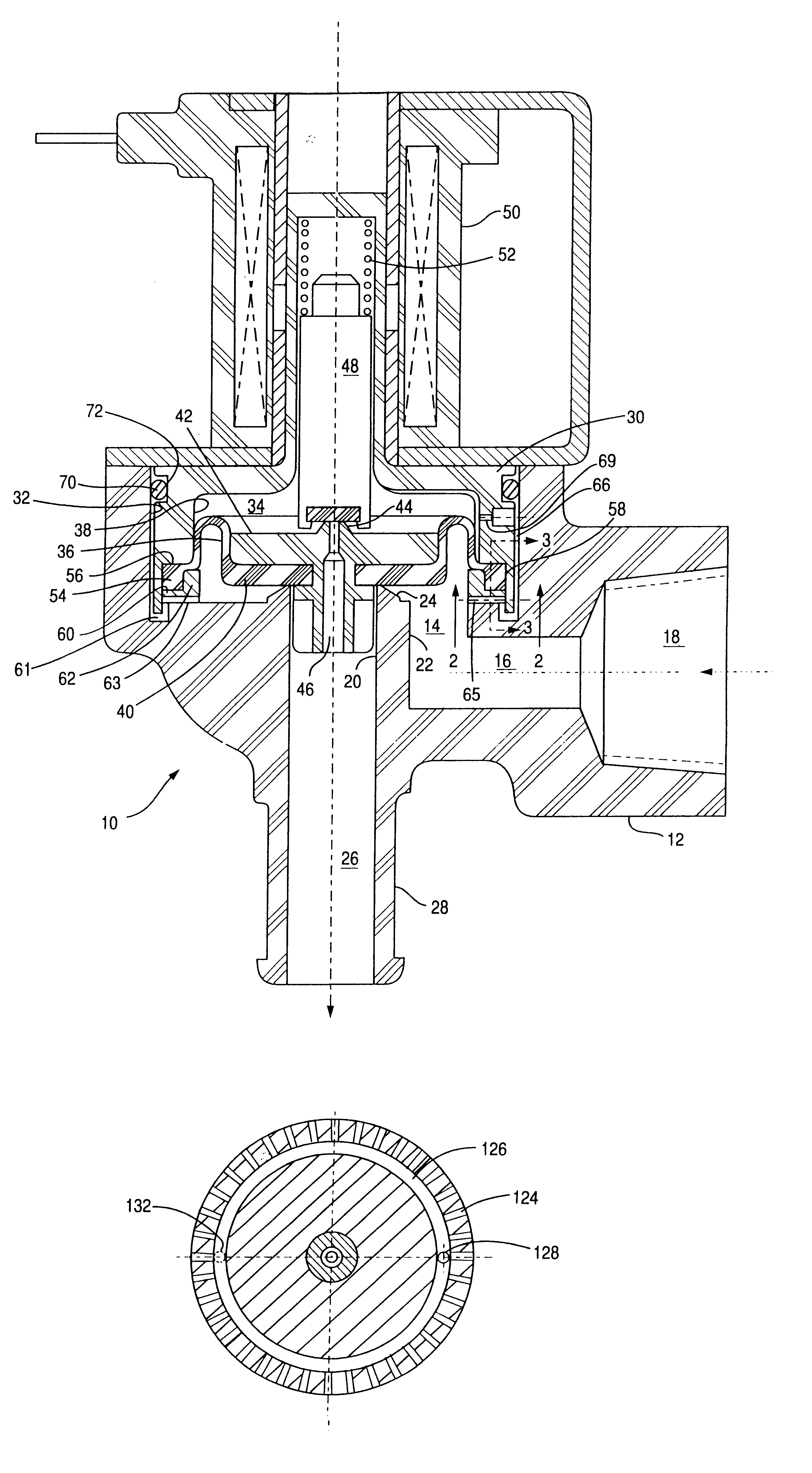
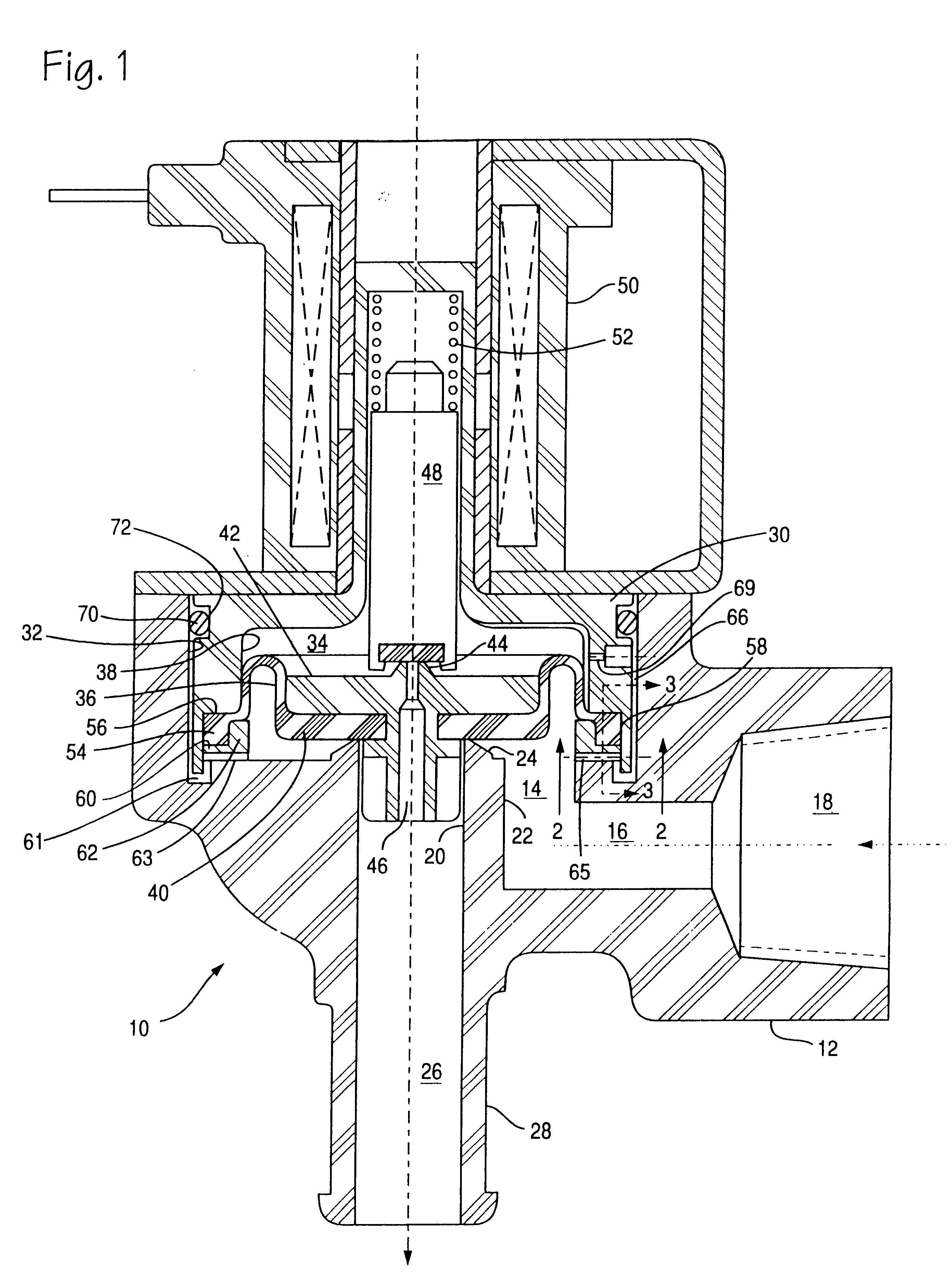
Reference to FIG. 1, the valve assembly of the present invention is indicated generally indicated at 10 and has a housing 12 of a plastic or metal material, and a main valve chamber 14 which communicates with passage 16 and inlet 18. An outlet bore 20 is formed in a boss 22 extending into chamber 14 and terminates in valve seat 24. Outlet bore 20 communicates with outlet passage 26 to permit fluid flow to outlet 28 when valve 10 is operated to open.

A cover 30 having a bore 38 is received within bore 32 of the housing 12 and forms a pilot chamber 34 with flexible diaphragm 36 and bore 38. Pilot chamber 34 is separated from chamber 14 by flexible diaphragm 36, which has a main valve member 40 for movably contacting valve seat 24. Valve member 40, comprising the central portion of flexible diaphragm 36 has received therethrough an insert 42 which extends into bore 20 for sliding engagement with the wall thereof to thus act as a guide for movement of valve member 40. The pilot chamber s...


PUM


Abstract

An improved foreign particle resistant valve assembly having a pressure responsive diaphragm main valve member activated by a pilot valve which controls flow through small orifice passages whereby pressure forces are created across the diaphragm main valve member to permit and prevent flow through the main flow section of the valve. Several arrangements illustrate various configured foreign particle-screening passages that protect the pilot valve orifice passages from blockage. The screening may be an integral part of the valve body or may be a removable member to facilitate cleaning or manufacture, and may be adapted to metallic or plastic valves. Other embodiments provide the means to enlarge a pilot pressure drop orifice passage which would then be less susceptible to foreign particle blockage and could also be combined with the screening passage means of the first embodiment.

Description

BACKGROUND OF INVENTIONThe present invention relates primarily to improvements in the prevention of foreign particle blockage of the small pilot passages in pilot operated valves where the pilot actuator controls flow through an orifice to create pressure differential forces across a flexible diaphragm which acts as a main valve to permit and prevent flow through the main flow ports. These types of valves are economical in cost and are used in many applications and the state of art of their operation is well known, as is their susceptibility to malfunction when their relatively small pilot passages become blocked by foreign particles or other contaminants.Special attention is therefore paid to provide the best possible means for protection of these pilot flow sections from foreign particle contamination. Use of wire screening at the main flow inlet port does not offer full protection for these pilot passages as this screen size is necessarily made large to only trap major particles ...

Claims


Application Information

Patent Timeline
Patent Type & Authority Patents(United States)
IPC IPC(8): F16K31/36F16K31/40
CPCF16K31/404
Inventor KOLZE, LAWRENCE A.
Owner KOLZE
Why Eureka
Try Eureka