
Close/intra-formation positioning collision avoidance system and method

a collision avoidance and intra-formation technology, applied in direction finders, navigation instruments, instruments using radio waves, etc., can solve the problems of reducing the effectiveness of maintaining unable to fly imc, and unable to maintain precise position/separation criteria with respect to other aircraft and obstacles, so as to reduce the amount of rf interference and reduce the range

Inactive Publication Date: 2002-10-01
L 3 COMM CORP
View PDF14 Cites 108 Cited by
  • Summary
  • Abstract
  • Description
  • Claims
  • Application Information

AI Technical Summary

Problems solved by technology

Furthermore, collision avoidance is a problem for both military and commercial aircraft alike.
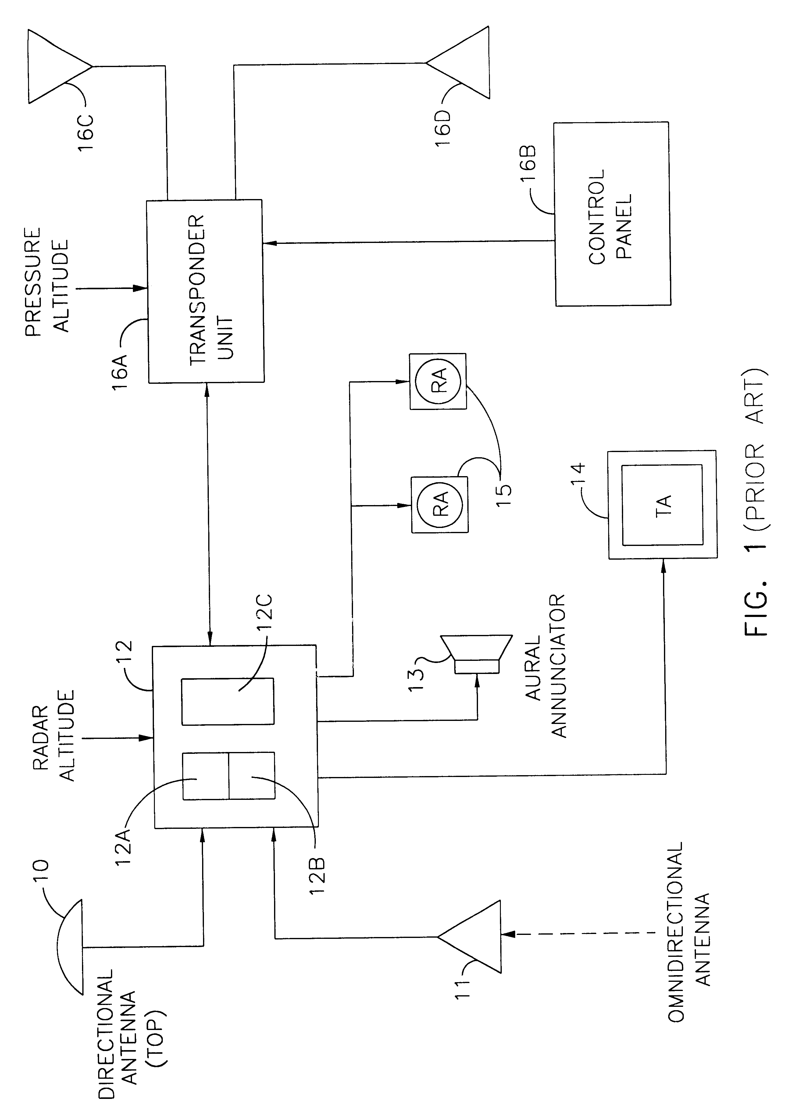
In addition, a large, simultaneous number of TCAS interrogations from close-in formation aircraft members generate significant radio frequency (RF) interference and could potentially degrade the effectiveness of maintaining precise position / separation criteria with respect to other aircraft and obstacles.
Also, the system is to be compatible (primarily because of cost issues) with current station keeping equipment (SKE) systems or they will not be able to fly IMC formation with SKE-equipped aircraft.
First, once an aircraft joins the formation, the ETCAS does not itself or in conjunction with any other on-board system maintain aircraft position and separation within the formation.
Second, the ETCAS Vertical Speed Indicator / Traffic Resolution Alert (VSI / TRA) display does not annunciate relative velocity (range-rate) of the lead formation and member aircraft.
Transponder interrogations and the resulting Mode-S transponder replies significantly increase RF reception interference with a large formation of aircraft and could degrade the effectiveness of maintaining precise position / separation criteria.
In addition, the increased composite level of RF severely inhibits a large formation from covertly traversing airspace undetected.
Another problem is presented in previous systems wherein station keeping equipment (SKE) on existing military aircraft can support a formation of only 16 aircraft.

Method used


Image

  • Close/intra-formation positioning collision avoidance system and method
  • Close/intra-formation positioning collision avoidance system and method
  • Close/intra-formation positioning collision avoidance system and method

Examples


Embodiment Construction

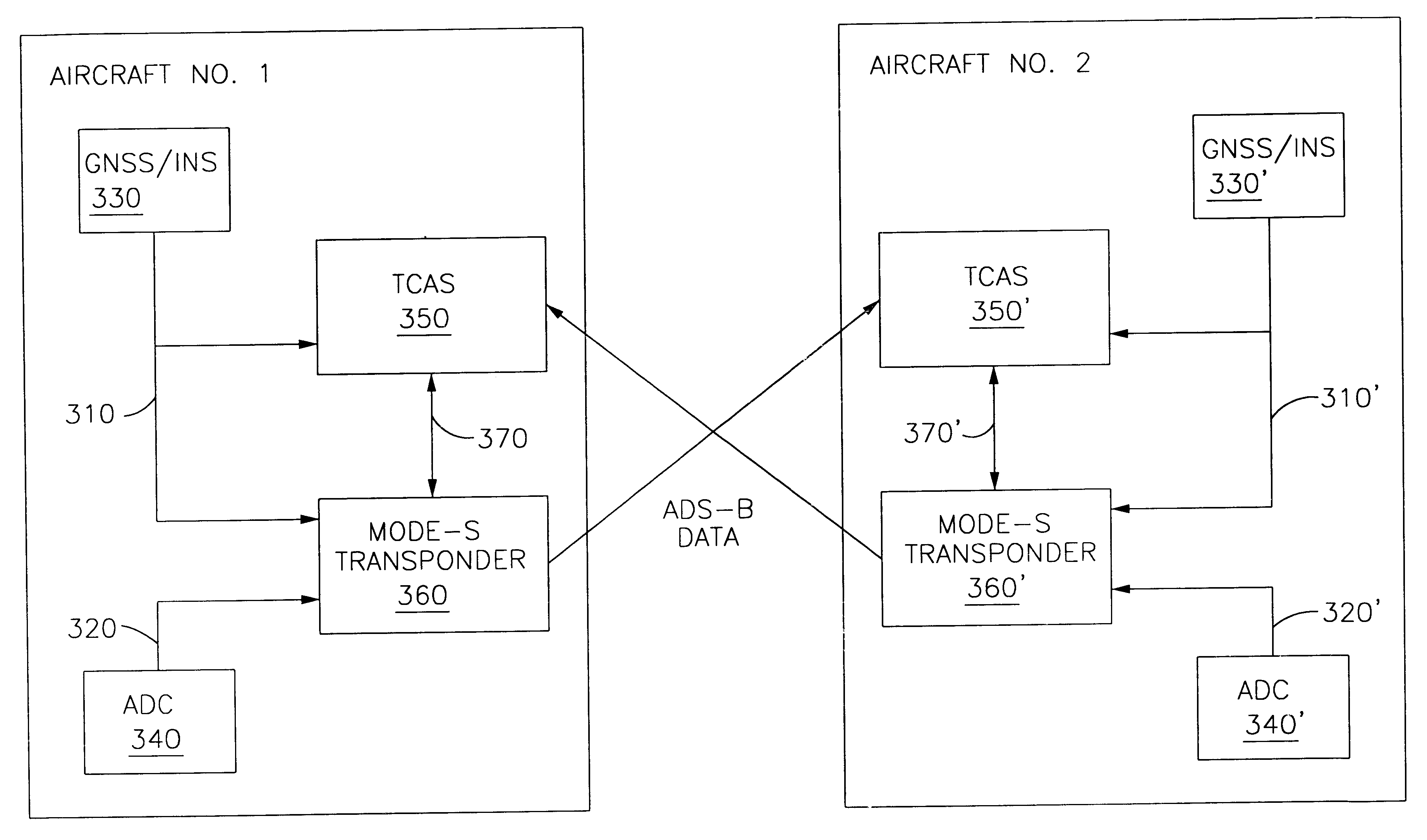
A passive Collision Avoidance System (CAS) is implemented by the present invention to maintain selectable separation between formation cells and follower aircraft within each cell using an integrated control system. The passive CAS is attained by the present invention using centralized control and decentralized execution of multiple aircraft formation cells. The present invention uses TCAS and Global Positioning System (GPS) Squitter data from a Mode-S transponder. The terms GPS squitter, Mode-S squitter, and ADS-B mean the same thing and are used interchangeably throughout the description of the present invention to describe extended data transmission.

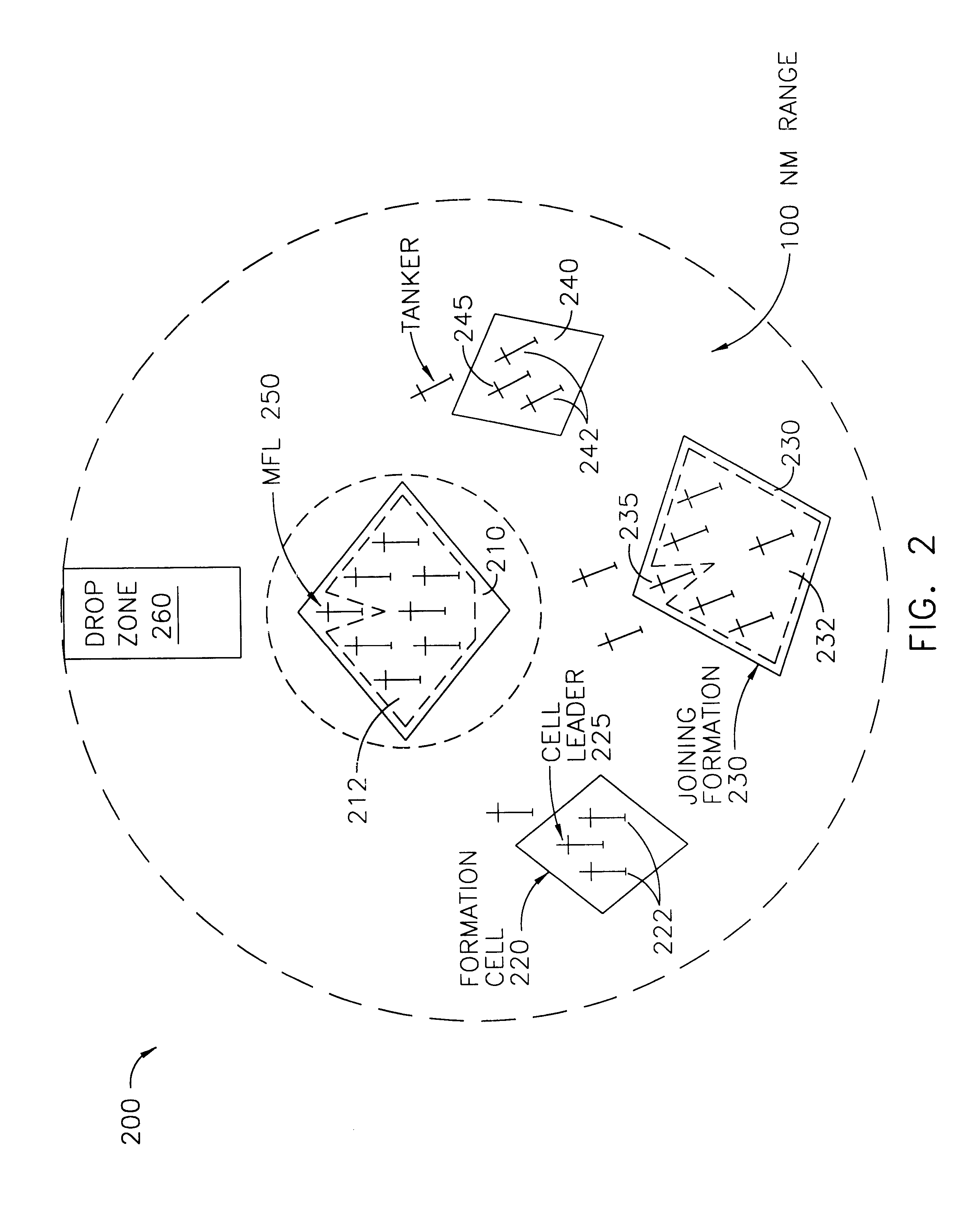
Assembling a large number of formation aircraft (e.g., for a massive size military airdrop in IMC and night flying conditions) is a positioning / separation control problem that is implemented by the present invention in two parts:

1) Modification or augmentation of a conventional TCAS, e.g., Honeywell TCAS-2000 (product no. RT-951), to ...


PUM


Abstract

A passive Traffic Alert and Collision Avoidance System (TCAS) and method is based on receiving and processing Mode-S transponder messages without the TCAS computer having to interrogate the transponders of the respective aircraft flying in formation (i.e., a passive TCAS). A TCAS computer and Mode-S transponder are used to provide distributed intra-formation control among multiple cells of aircraft flying in formation or close-in. The Mode-S transponder provides ADS-B Global Positioning System (GPS) squitter data to the TCAS computer; the TCAS computer receives and processes the data without having to interrogate the transponders of the multiple cells of aircraft. The method and system allow a safe separation between 2 to 250 aircraft flying in formation at selectable ranges.

Description

II. BACKGROUND OF THE INVENTIONThe present invention relates generally to the field of avionics for collision avoidance systems (CAS). More specifically, the present invention relates generally to airborne traffic alert and collision avoidance systems and transponders. The collision avoidance system described herein has the capability to position and separate aircraft in a large flight formation in, for example, night / instrument meteorological conditions.Spurred by the collision of two airliners over the Grand Canyon in 1956, the airlines initiated a study of collision avoidance concepts. By the late 1980's, a system for airborne collision avoidance was developed with the cooperation of the airlines, the aviation industry, and the Federal Aviation Administration (FAA). The system, referred to as Traffic Alert and Collision Avoidance System II (TCAS II) was mandated by Congress to be installed on most commercial aircraft by the early 1990's. A chronology of the development of airborn...

Claims


Application Information

Patent Timeline
Patent Type & Authority Patents(United States)
IPC IPC(8): G01S13/00G01S13/93B64D45/00G01C23/00G01S13/75G01S13/76G01S13/79G01S13/933G01S19/14G01S19/49G08G5/00G08G5/04
CPCG01C23/00G01S13/9303G01S13/933G01S13/93
Inventor FRAZIER, JAMES A.JONGSMA, KENNETH R.STURDY, JAMES T.
Owner L 3 COMM CORP
Learn More