

Base materials for a clear protective overcoat on inkjet images
a technology of clear protective overcoat and inkjet image, which is applied in the direction of inking apparatus, printing mechanisms, instruments, etc., can solve the problems of brittle coatings with relatively poor flexibility, dramatic increase of melt viscosity, and low abrasion resistan
Inactive Publication Date: 2002-10-15
HEWLETT PACKARD DEV CO LP
View PDF10 Cites 20 Cited by
- Summary
- Abstract
- Description
- Claims
- Application Information
AI Technical Summary
Problems solved by technology
As a result, brittle coatings with relatively poor flexibility and hence inferior abrasion resistance are likely.
Furthermore, covalent cross-linking during the overcoat fusing process would be irreversible, thus leading to a dramatic increase of melt viscosity.
This in turn would lead to an overcoat with poor gloss and non-uniform thickness.
There has previously been no attempt to use thermoplastic ionomers as a coating material for printed images, since the extrusion and / or blow molding processes conventionally used with ionomers do not lend themselves to such application.
Styrenated acrylics have the disadvantage of poor fusibility (high softening temperature) and poor gloss and clarity.
Low molecular weight polyesters have very poor mechanical properties (no flexibility and abrasion resistance) and poor resistance to inkjet ink solvents.
Polyolefins have poor abrasion resistance, poor clarity and gloss as well as a waxy feel.
Method used
View moreImage
Smart ImageViewing Examples


Examples
example 1
A powder form of ethylene-methacrylic acid / salt copolymer, a thermoplastic ionomer, was used as clear toner. The clearcoat particles were properly charged within an electrostatic developer and then electrostatically projected upon inkjet printed image. The mass level of the projected clearcoat particles was sufficient to provide the necessary overcoat thickness. The overcoating powder layer was then fused using a heated roller (.about.120-140.degree. C.).
The resulting clear overcoat layer (.about.1.0-3.0 mil) was tough, very flexible and scratch resistant. It was of high clarity and gloss (.about.70-80%). The overcoat thus obtained was resistant to water and organic solvents at ambient temperature.
Login to View More PUM
| Property | Measurement | Unit |
|---|---|---|
| Composition | aaaaa | aaaaa |
| Polarity | aaaaa | aaaaa |
| Color | aaaaa | aaaaa |
Abstract
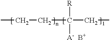
The use of thermoplastic ionomers to form a clear protective overcoating layer over an offset, inkjet or xerographic printed image.
Description
The present invention relates to the use of thermoplastic ionomer-based clear toners to create a clear overcoating for inkjet printed images.BACKGROUND OF INVENTIONThe use of inkjet printing systems has grown dramatically in recent years. This growth may be attributed to substantial improvements in print resolution and overall print quality coupled with appreciable reduction in cost. Today's inkjet printers offer acceptable print quality for many commercial, business, and household applications at costs fully an order of magnitude lower than comparable products available just a few years ago. Notwithstanding their recent success, intensive research and development efforts continue toward improving inkjet print quality, while further lowering cost to the consumer.An inkjet image is formed when a precise pattern of dots is ejected from a drop-generating device known as a "printhead" onto a printing medium. The typical inkjet printhead has an array of precisely formed nozzles located o...
Claims
Login to View More Application Information
Patent Timeline
 IPC IPC(8): B41J2/355B41M7/00B41J11/00C09D123/08C09D123/00G03G8/00B41J7/00B41M5/00C09D133/02
CPCB41J2/355B41J11/0015B41M7/0027C09D123/08G03G8/00B41J2202/34
InventorKASPERCHIK, VLADEK PKWASNY, DAVID M
OwnerHEWLETT PACKARD DEV CO LP