System and method using impulse radio technology to track and monitor people needing health care

a technology of impulse radio and monitoring system, applied in the field of health care, can solve the problems of difficult radio contact between electronic monitors (including standard radio transmitters) and radio receivers at certain locations, overcrowded hospitals, and high hospitalization costs of all these peopl

Inactive Publication Date: 2002-10-15
HUMATICS CORP
View PDF20 Cites 184 Cited by
  • Summary
  • Abstract
  • Description
  • Claims
  • Application Information

AI Technical Summary

Problems solved by technology

The number of people requiring health care has increase dramatically in the past few years, resulting in overcrowded hospitals.
The hospitalization of all these people is very expensive, which has lead the health care industry to demand that some of these patients be moved from the hospital to an intermediary care-giving facility such as a nursing home, or to their homes.
However, problems have arisen in the past with this scenario because with standard radio transmissions there are often problematical "dead zones" within a home that may trigger a false alarm.
The "dead zones" may be attributable to the closed structure of the home, which can make it difficult for the electronic monitor (including the standard radio transmitter) to maintain radio contact with a standard radio receiver at certain locations in the home.
As such, the medical personnel may receive a false alarm that the patient's electronic monitor is no longer communicating to the standard radio receiver even though the patient does not need medical assistance.
In particular, the false alarm may be triggered because the standard radio signals sent from the standard radio transmitter cannot penetrate a certain wall or floor within the home and reach the standard radio receiver.
The "dead zones" may also be attributable to multipath interference which can be very problematic in a closed structure such as a home.
Multipath interference is the error caused by the interference of a standard radio signal that has reached a standard radio receiver by two or more paths.
Essentially, the standard radio receiver may not be able to demodulate the standard radio signal because the transmitted radio signal effectively cancels itself by reaching the standard radio receiver at different times.
Any practical implementation will deviate from the ideal mathematical model by some amount.
This is especially true for microwave implementations, where precise waveform shaping is difficult to achieve.
It can also be observed from FIG. 2A that impulse radio systems typically have very low average duty cycles resulting in average power significantly lower than peak power.
Since a data bit may comprise hundreds of pulses, this represents a substantial attenuation of the unwanted channel.
Clearly, if there were a large number of impulse radio users within a confined area, there might be mutual interference.
This is critical as any other signals within the band occupied by an impulse signal potentially interfere with the impulse radio.
Since there are currently no unallocated bands available for impulse systems, they must share spectrum with other conventional radio systems without being adversely affected.
Without coding, the cross correlation would sample the interfering signal 402 with such regularity that the interfering signals could cause significant interference to the impulse radio receiver.
However, when the transmitted impulse signal is encoded with the code dither (and the impulse radio receiver template signal 406 is synchronized with that identical code dither) the correlation samples the interfering signals non-uniformly.
This results in possible summation or possible cancellation, depending on the specific propagation to a given location.
In mobile systems, this results in wild signal strength fluctuations as a function of distance traveled, where the changing mix of multipath signals results in signal strength fluctuations for every few feet of travel.
Narrow band systems, on the other hand, are limited to the modulation envelope and cannot easily distinguish precisely which RF cycle is associated with each data bit because the cycle-to-cycle amplitude differences are so small they are masked by link or system noise.
Such `random-like` codes are attractive for certain applications since they tend to spread spectral energy over multiple frequencies while having `good enough` correlation properties, whereas designed codes may have superior correlation properties but have spectral properties that may not be as suitable for a given application.

Method used


Image

  • System and method using impulse radio technology to track and monitor people needing health care
  • System and method using impulse radio technology to track and monitor people needing health care
  • System and method using impulse radio technology to track and monitor people needing health care

Examples


first embodiment

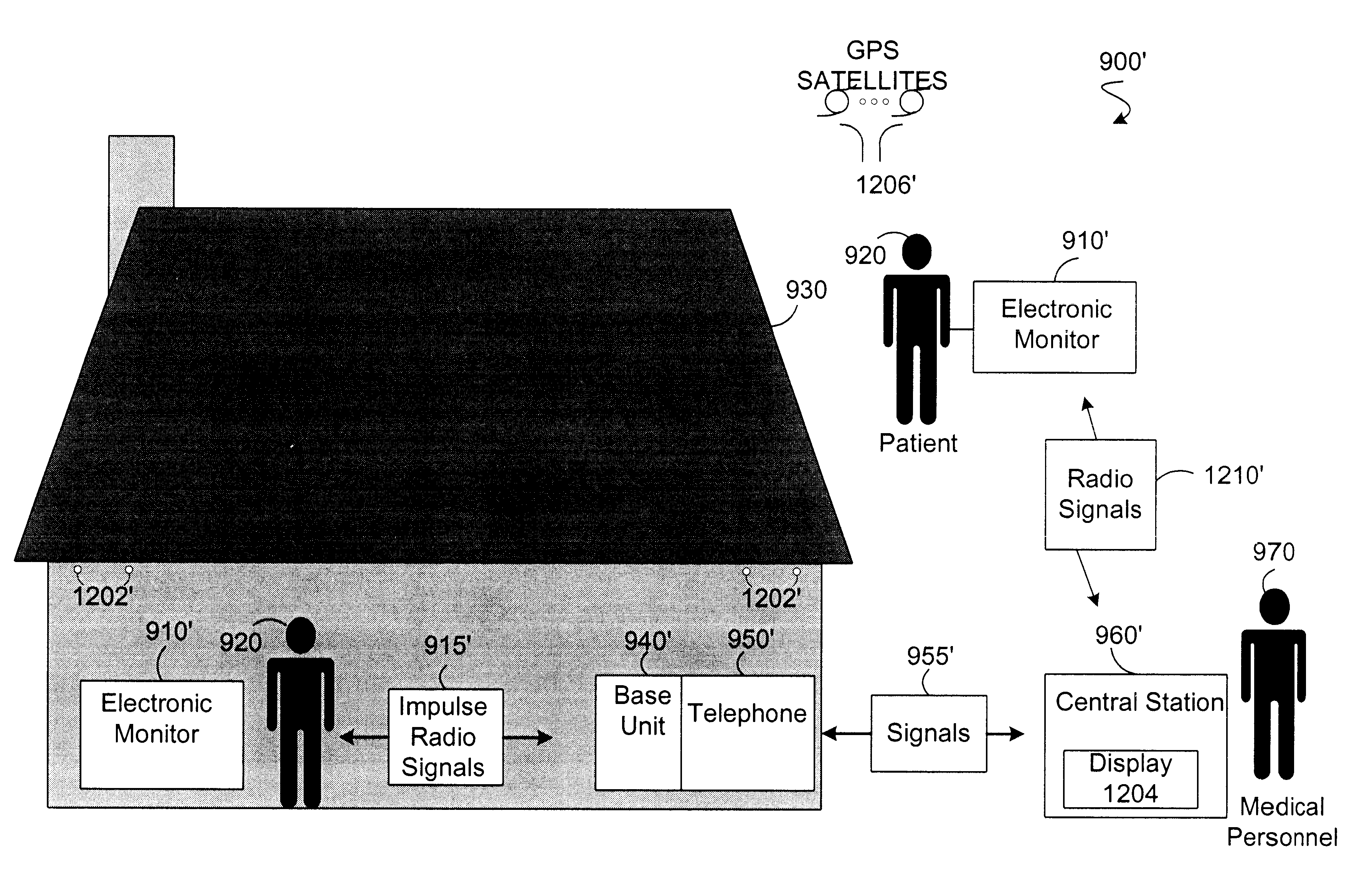
Referring to FIG. 9, there is a diagram illustrating the basic components of the system 900 in accordance with the present invention. The system 900 includes an electronic monitor 910 that can be carried by a patient 920 in a building such as a hospital, a nursing home or a home 930 (as shown). The electronic monitor 910 (including an impulse radio transmitter 602) can continually or periodically transmit an impulse radio signal 915 to a base unit 940 (including an impulse radio receiver 702). The base unit 940 is coupled to or incorporated within a telephone 950 (e.g., land-based phone or wireless phone).

third embodiment

If the base unit 940 fails to receive the impulse radio signal 915, then the base unit 940 interacts with the telephone 950 to send an alarm signal 955 to a central station 960. Of course, the base unit 940 and telephone 950 would not be required if the electronic monitor 910 could communicate directly with the central station 960 (see third embodiment).

In response to receiving the alarm signal 955, the central station 960 initiates a visual alarm and / or audio alarm to inform medical personnel 970 that the patient 920 may need medical assistance. For instance, if the patient 920 wanted medical assistance they could press a panic button 912 (see FIG. 10) on the electronic monitor 910 which would disable the impulse radio transmitter 602 and stop the transmission of the radio signal 915 to the base unit 940.

If the base unit 940 receives the impulse radio signal 915, then the base unit 940 does not interact with the telephone 950 to send the alarm signal 955 to the central station 960....

second embodiment

Referring to FIG. 14, there is a flowchart illustrating the basic steps of a preferred method 1400' for tracking and monitoring a patient 920 in accordance with the present invention. Beginning at step 1402', the electronic monitor 910' is attached to the patient 920 with the aid of the fastening mechanism 1002'. The fastening mechanism 1002' typically secures the electronic monitor 910' to an arm of the patient 920.

At step 1404', the sensor 1304' is coupled to the electronic monitor 910' in a manner so as to enable the monitoring of at least one vital sign of the patient 920. As described above, the sensor 1304' is capable of functioning as a temperature monitor, heart rate monitor, blood pressure monitor, blood monitor and / or a perspiration monitor. As such, the central station 960' can monitor one or more vital signs to detect health related problems of the patient 920.

At step 1406', the electronic monitor 910' can determine the location of a patient 920 within the home 930 (for ...


PUM


Abstract

A system, electronic monitor and method are provided that utilize impulse radio technology to alert medical personnel when a patient needs medical assistance. In addition, the present invention includes a system, electronic monitor and method that utilize the communication capabilities and positioning capabilities of impulse radio technology to enable medical personnel to monitor one or more vitals signs of a patient and/or to enable medical personnel to determine a current a position of a patient in a building such as a hospital, nursing home or their home.

Description

1. Field of the InventionThe present invention relates in general to the health care field and, in particular, to a system, electronic monitor and method capable of using impulse radio technology to monitor and / or track people that may need medical assistance.2. Description of Related ArtThe number of people requiring health care has increase dramatically in the past few years, resulting in overcrowded hospitals. The hospitalization of all these people is very expensive, which has lead the health care industry to demand that some of these patients be moved from the hospital to an intermediary care-giving facility such as a nursing home, or to their homes. The moved patient still requires at a minimum the ability to contact and alert medical personnel should they need medical assistance.For instance, the patient that is sent to their home may wear an electronic monitor that includes a panic button. The electronic monitor may also include a radio transmitter that is designed to contin...

Claims


Application Information

Patent Timeline
Patent Type & Authority Patents(United States)
IPC IPC(8): G01S13/00G01S13/76G01S13/42H04B1/69
CPCG01S13/42G01S13/76H04B1/7163H04B2001/6908
Inventor RICHARDS, JAMES L.FULLERTON, LARRY W.KELLY, DONALD A.MEIGS, DAVID C.PAYMENT, TIMOTHY T.FINN, JAMES S.TUCKER, WILLIAM J.WELCH, JR., WILLIAM D.
Owner HUMATICS CORP
Why Eureka
Try Eureka