
Method and apparatus for executing a function within a composite icon and operating an object thereby

Inactive Publication Date: 2002-10-22
LINKEDIN
View PDF11 Cites 380 Cited by
  • Summary
  • Abstract
  • Description
  • Claims
  • Application Information

AI Technical Summary

Benefits of technology

It is another object of this invention to improve the user operability of a software by grouping a plurality of functions intimately related to a user in an icon area which is expressed by a single appearance image.
It is a further object of this invention to provide a GUI environment which is capable of preventing an erroneous operation by a user beforehand by changing the entire appearance (or a part of appearance) of an icon depending on the position of a mouse pointer on the icon and explicitly notifying the operator of a function which is to be executed when clicked in that position before the function is executed.
It is a further object of this invention to provide a GUI environment which allows an operator to dynamically select a function group which the operator desires.

Problems solved by technology

Thus, as the number of the kinds of functions required for a software increases, the number of icons on the screen increases correspondingly leading to a problem that an area is occupied by the icons while an area for the essential function of a software (main window) is narrowed.
If the size of an icon is reduced in order to solve this problem, the graphic presentation of an icon becomes scanty and makes the content of the function discernible to a user.
As a result, a problem is induced in that adoption of many functions leads to deterioration of the operability of an application.
However, because each of a plurality of icons existing on a single tool pallet has a single function assigned in respective icon area, the size of an icon is limited when the number of the kinds of functions increases and it was sometimes difficult to intuitively judge in which tag a desired icon exists.
However, the display (external appearance) of a tool is modified only after an area is selected in this technology so that a problem was accompanied in that the operator was not able to see what function was assigned to each area before the function was executed.
However, because the external appearance is not changed in this technology, this technology was not able to solve a problem that the graphic expression to describe the function became scanty as the number of the kinds of functions required for a software increased.

Method used


Image

  • Method and apparatus for executing a function within a composite icon and operating an object thereby
  • Method and apparatus for executing a function within a composite icon and operating an object thereby
  • Method and apparatus for executing a function within a composite icon and operating an object thereby

Examples


Embodiment Construction

A. Hardware Configuration

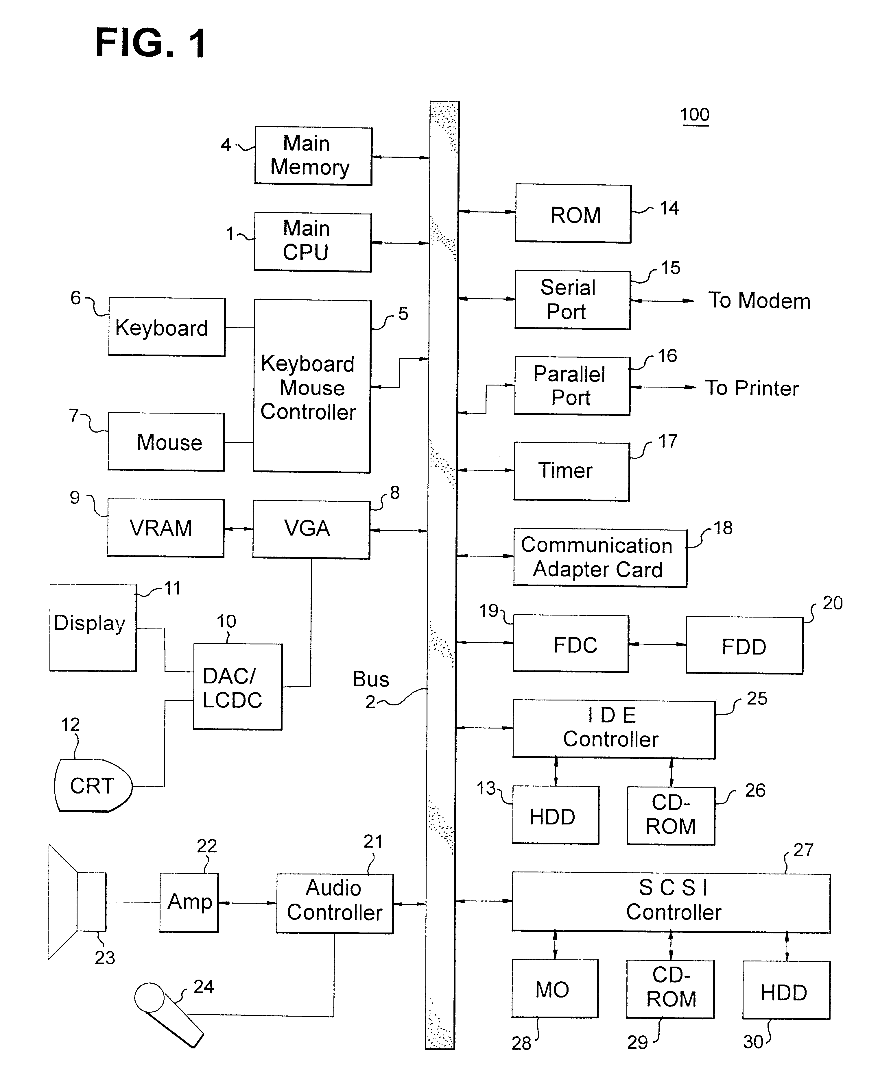
An embodiment of this invention is now described with reference to the drawings. Referring to FIG. 1, a schematic diagram of an embodiment of a hardware configuration of a data processing apparatus 100 which is used in this invention is shown. The data processing apparatus 100 comprises a central processing unit (CPU) I and a memory 4, which are connected via bus 2 to timer 17. The CPU 1 and the main memory 4 are connected to a hard disk device 13 and CD-ROM 26 as auxiliary storage via IDE controller 25 and bus 2. A floppy disk device 20 is connected to the bus 2 through a floppy disk controller 19. Other storage medium driving devices, such as MO 28, CD-ROM 29 and HDD 30, are connected via SCSI Controller 27 and bus 2 to CPU 1 and main memory 4.

A floppy disk device (or a storage medium such as MO and CD-ROM) is inserted in the floppy disk device 20 (or a storage medium driving device such as MO and CD-ROM). A computer program code which gives instructions t...


PUM


Abstract

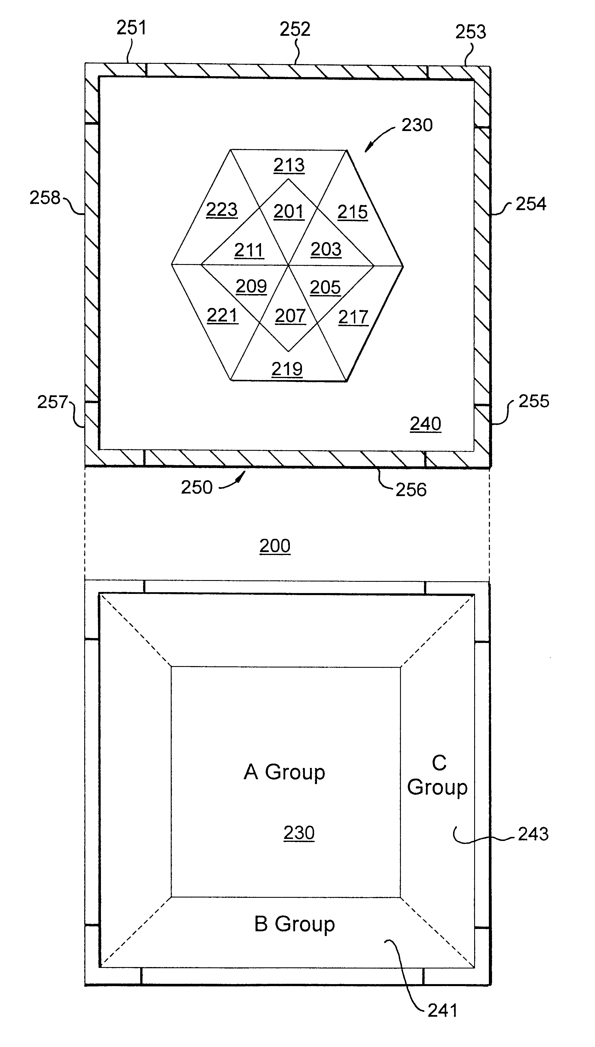
The present invention is directed to explaining functions with a rich graphical expression even when the number of kinds of functions required for a software increases.More particularly, a plurality of function areas 201-223 are defined in a composite icon area of the present invention. An appearance image is associated to each function area and, when a mouse pointer comes across a function area, appearance images associated to that function area are displayed as appearance images of a composite icon. A function is also associated to each function area and, when a mouse is clicked on a function area, a function which is associated to that function area is executed. The set of the function area may be changed by changing the size of a composite icon, an operation to switch the group of functions, or selection of an object to be operated upon.

Description

1. Technical FieldThis invention relates to a method of operating a GUI (Graphical User Interface) screen of an information processing apparatus and more particularly, to a function selecting method which allows a user to easily indicate execution of different functions.2. Prior ArtIn a software having a conventional GUI, a single icon is assigned a single function and an assigned function is executed by clicking an icon with a mouse.Thus, as the number of the kinds of functions required for a software increases, the number of icons on the screen increases correspondingly leading to a problem that an area is occupied by the icons while an area for the essential function of a software (main window) is narrowed.If the size of an icon is reduced in order to solve this problem, the graphic presentation of an icon becomes scanty and makes the content of the function discernible to a user. As a result, a problem is induced in that adoption of many functions leads to deterioration of the o...

Claims


Application Information

Patent Timeline
IPC IPC(8): G06F3/033G06F3/0481G06F3/0482G06F3/0486
CPCG06F3/0481G06F3/14
Inventor KINOE, YOHSUKEOKAMOTO, KOHSUKEMURANAKA, NAOFUMITAKEMURA, TSUKASAMATSUDA, MINAKOUCHIYAMA, NORIMASA
Owner LINKEDIN
Learn More