
Sheet feeding apparatus and image processing apparatus

a technology of image processing apparatus and feeding apparatus, which is applied in the direction of transportation and packaging, thin material processing, and article separation, etc., can solve the problems of fog in recording image quality, sheet back tension in recording section, and the inability of the roller to make perfectly synchronized feeding

Inactive Publication Date: 2002-10-29
CANON KK
View PDF4 Cites 22 Cited by
  • Summary
  • Abstract
  • Description
  • Claims
  • Application Information

AI Technical Summary

Benefits of technology

According to this sheet feeding apparatus, since the intermediate conveyance roller normally rotating in the sheet feeding direction can project in and escape from the sheet conveyance route, the sheet can be conveyed smoothly without exerting any load due to shifts in operation of the drive system.
According to this sheet feeding apparatus, since the locking mechanism locks and unlocks the one-way clutch transmitting drive to the feeding roller in association with the motion of the intermediate conveyance roller, the sheet can be conveyed smoothly in releasing loads to the intermediate conveyance roller as well as the feeding roller when the sheet enters in the image processing section.

Problems solved by technology

However, both rollers cannot make perfectly synchronized feeding due to various factors such as pulsation movements of the drive system and differences in inertia of the drive system, and therefore, slight disorders in feeding may occur, creating fogs in recording image quality.
With this apparatus, however, though feeding disorders due to asynchrony between the above both rollers can be avoided, the intermediate conveyance roller idles together with the conveyed sheet, thereby rendering the idling of the intermediate conveyance roller by itself loaded to the sheets, so that sheets may be subject to back tension in the recording section.
Accordingly, conveyance in the recording section by feeding roller becomes unstable, so that the recording images may be disordered, and in some cases, images may be shrunk in the feeding direction.

Method used


Image

  • Sheet feeding apparatus and image processing apparatus
  • Sheet feeding apparatus and image processing apparatus
  • Sheet feeding apparatus and image processing apparatus

Examples


first embodiment

Referring to the drawings, an embodiment of a recording apparatus to which the above means apply is described next. The recording apparatus is described as an image processing apparatus, but the same sheet feeding apparatus can be used in an image reading apparatus.

This embodiment is described with use of a serial type inkjet recording apparatus, and the recording apparatus uses, as a recording head, a disposable type recording head detachably attached to the recording apparatus.

Whole Structure

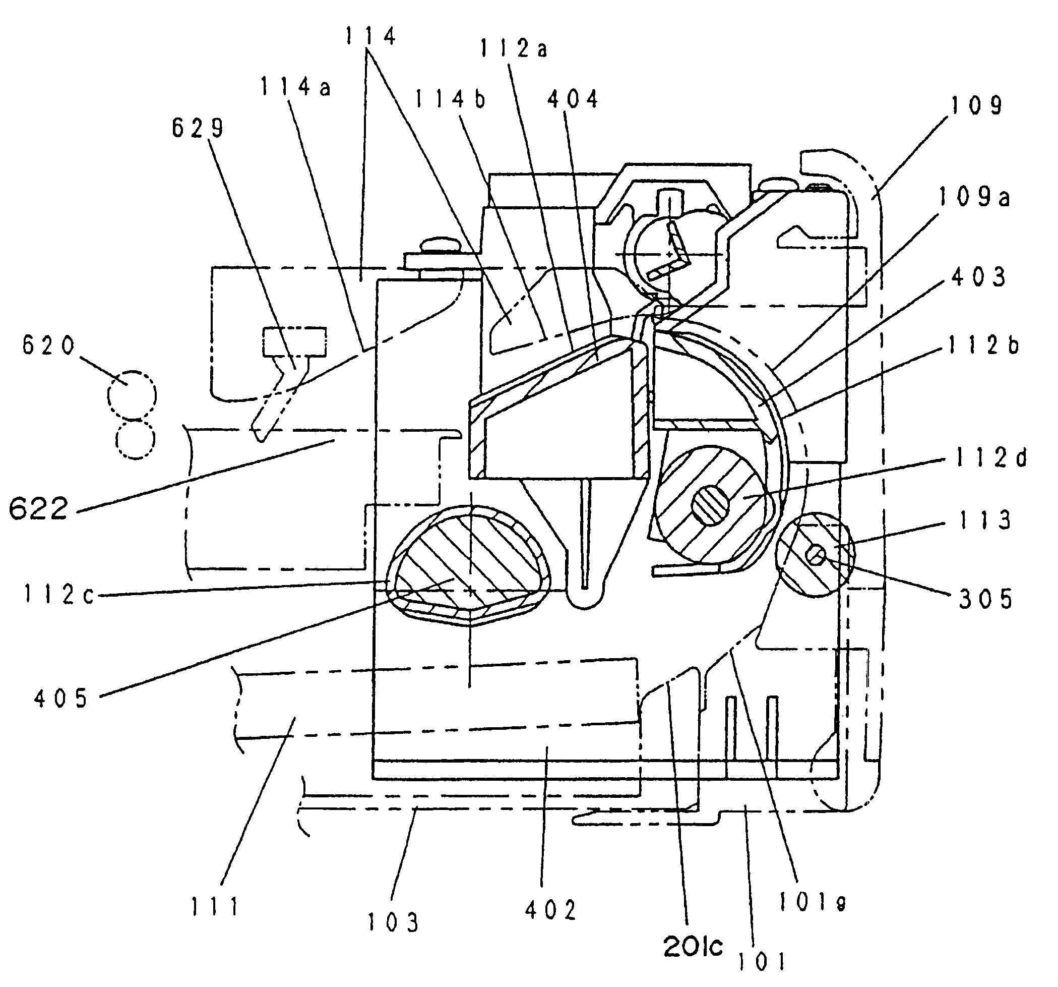
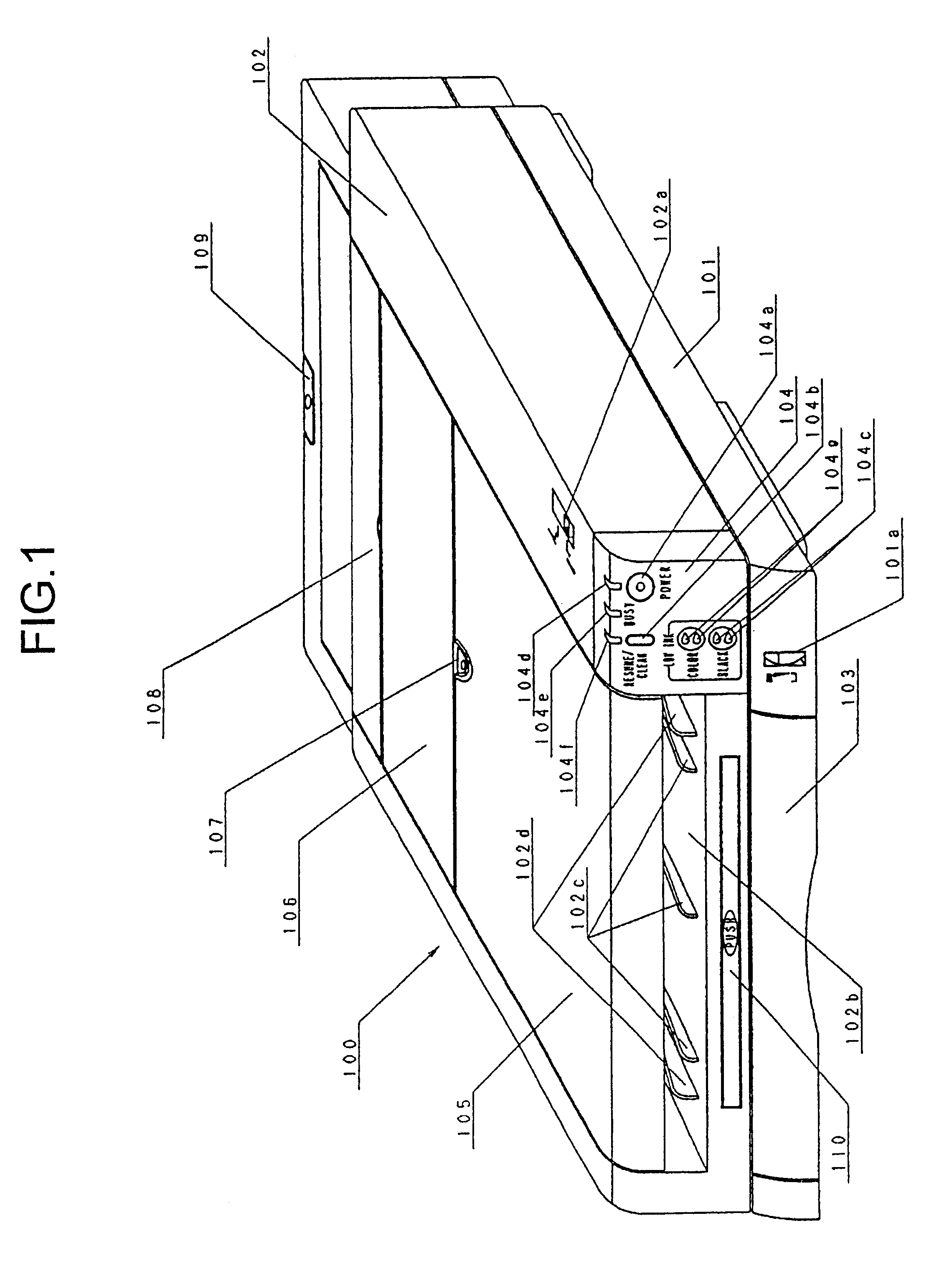
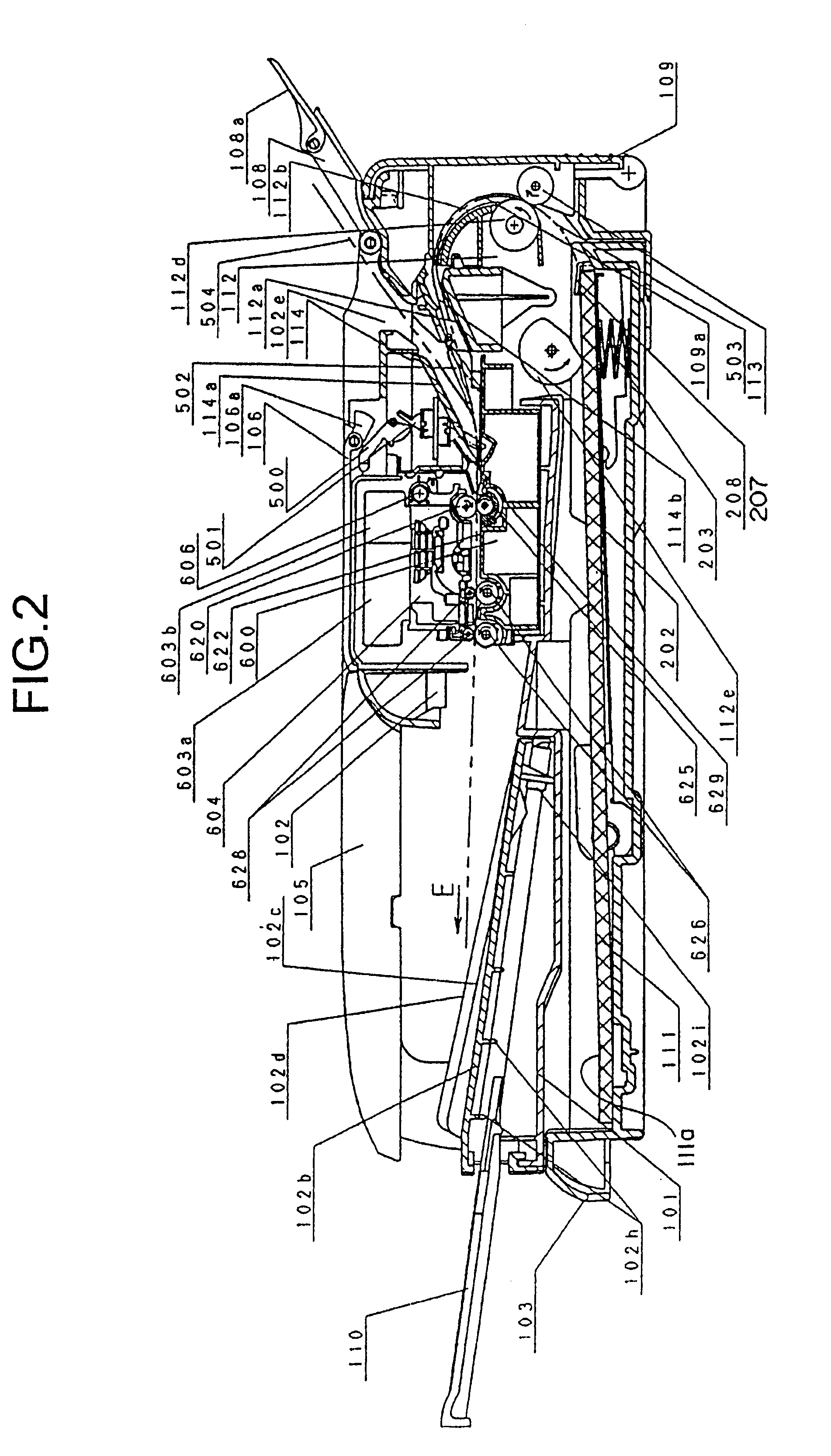
FIG. 1 is an eternal perspective view of the recording apparatus; FIG. 2 is a right cross section showing a sheet conveyance route of a recording sheet of a recording apparatus.

First of all, a basic structure of the recording apparatus is described in reference to FIG. 1 and FIG. 2.

In FIG. 1, numeral 101 is a base (bottom case) and is constituting a housing and chassis of the recording apparatus with a main casing 102.

Numeral 101a is an indicator portion which can show a sheet remaining amount...


PUM


Abstract

Present invention relates to a sheet feeding apparatus for conveying a sheet from a feeding roller to an image processing section, comprising an intermediate conveyance roller disposed between the feeding roller and the image processing section, a drive source providing a rotary drive force to the intermediate conveyance roller, an intermediate conveyance roller moving mechanism for moving the intermediate conveyance roller to be projecting in a sheet conveyance route so as to be conveyable of the sheet when the drive source is driven in one rotational direction and to be escaping from the sheet conveyance route when the drive source is driven in the other rotational direction and an intermediate conveyance roller normally feeding mechanism for rotating the intermediate conveyance roller in only one sheet feeding direction notwithstanding of the rotational direction of the drive source.

Description

1. Field of the InventionThis invention relates to a sheet feeding apparatus applicable to an image processing apparatus such as a photocopier, a printer, a facsimile machine, and the like and, more particularly, to a sheet feeding apparatus for feeding sheets to an image forming section and an image processing apparatus to which the sheet feeding apparatus is mounted.2. Description of Prior ArtAs a sheet feeding apparatus applying to an image processing apparatus such as a printer or the like, an apparatus has been known in which plural sheets are stacked and contained in feeding cassettes, in which a feeding roller formed in the apparatus body presses the top surface of the stacked sheets, in which the sheet is picked up and fed sheet by sheet from the topmost sheet of the stacked sheets by the rotation of the feeding roller, and in which the sheet is conveyed to an image processing apparatus (such as recording section) by intermediate conveyance roller.For example, with a convent...

Claims


Application Information

Patent Timeline
IPC IPC(8): B65H5/06
CPCB65H5/06B65H2403/421B65H2403/72B65H2404/144B65H2404/1442
Inventor SUGIMURA, HIDEO
Owner CANON KK
Learn More