Feed pump

a technology of feed pump and feed tube, which is applied in the direction of liquid fuel engine, marine propulsion, vessel construction, etc., can solve the problems of high noise emission, high noise emission, and different frequency of noise emission

Inactive Publication Date: 2002-10-29
VITESCO TECH GERMANY GMBH
View PDF14 Cites 22 Cited by
  • Summary
  • Abstract
  • Description
  • Claims
  • Application Information

AI Technical Summary

Benefits of technology

The slight variation in angular intervals between guide blades keeps the noise emissions in each of the rings of guide blades particularly low. Accordingly, none of the rings of guide blades generates a whistling sound. The variation in the angular intervals of the guide blades of the various rings prevents the noise emissions of each guide blade from adding up. The rings of guide blades therefore in each case generate noise emissions at different frequencies. Therefore, the noise emissions of the feed pump according to the present invention are distributed over a wide range of the audible frequency spectrum and are detected by the human ear as a uniform murmur. The feed pump according to the present invention consequently generates noise emissions which cause particularly little disturbance.
According to another embodiment of the present invention, overlaps of noise emissions of two rings of guide blades which may be generated accidentally due to the variation in the angular intervals, may be avoided in a simple way if the number of guide blades of the different rings varies.
The feed pump according to the present invention has, along with low disturbing noise emissions, particularly high efficiency if the number of guide blades of a radially inner one of two rings is smaller than the number of guide blades in the radially outer one of the two rings.
According to further embodiment of the present invention, noise emissions generated due to the rings of guide blades influencing one another via the fuel to be fed is avoided in a simple way if each feed channel is provided for connection to a specific consumer. For example, one feed channel may lead to a suction jet pump arranged within the fuel tank while the other feed channel is connected to a forward-flowline leading to an internal combustion engine of the motor vehicle. Moreover, one feed channel may be provided for suction intake directly from the fuel tank and the other feed channel for suction intake from a baffle. As a result, the flow of fuel from one ring of guide blades to a further ring is prevented, thereby avoiding the transmission and intensification of the noises within the feed pump.
The feed pump according to the present invention has particularly low noise emissions, along with high efficiency, if the angular intervals of the radially outer ring of guide blades of two rings vary relative to one another in the range of 8.degree. to 12.degree..

Problems solved by technology

A problem associated with the known feed pumps is that they generate very high noise emissions.
The noise emissions create a disturbing whistling sound.
The rings of guide blades therefore in each case generate noise emissions at different frequencies.

Method used


Image

  • Feed pump
  • Feed pump

Examples


Embodiment Construction

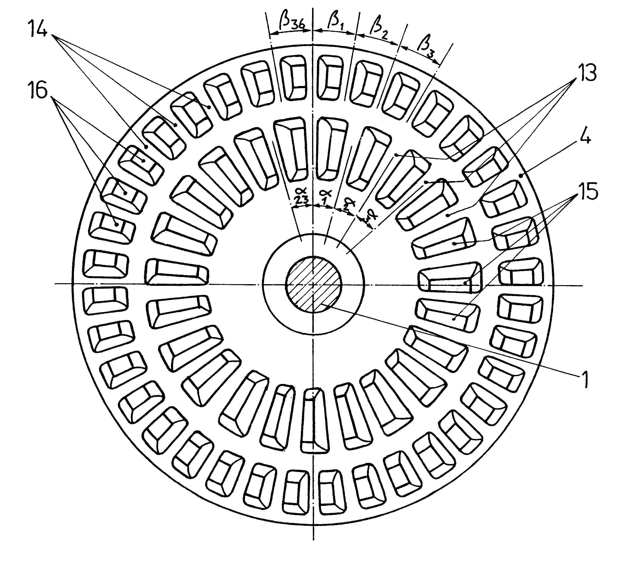
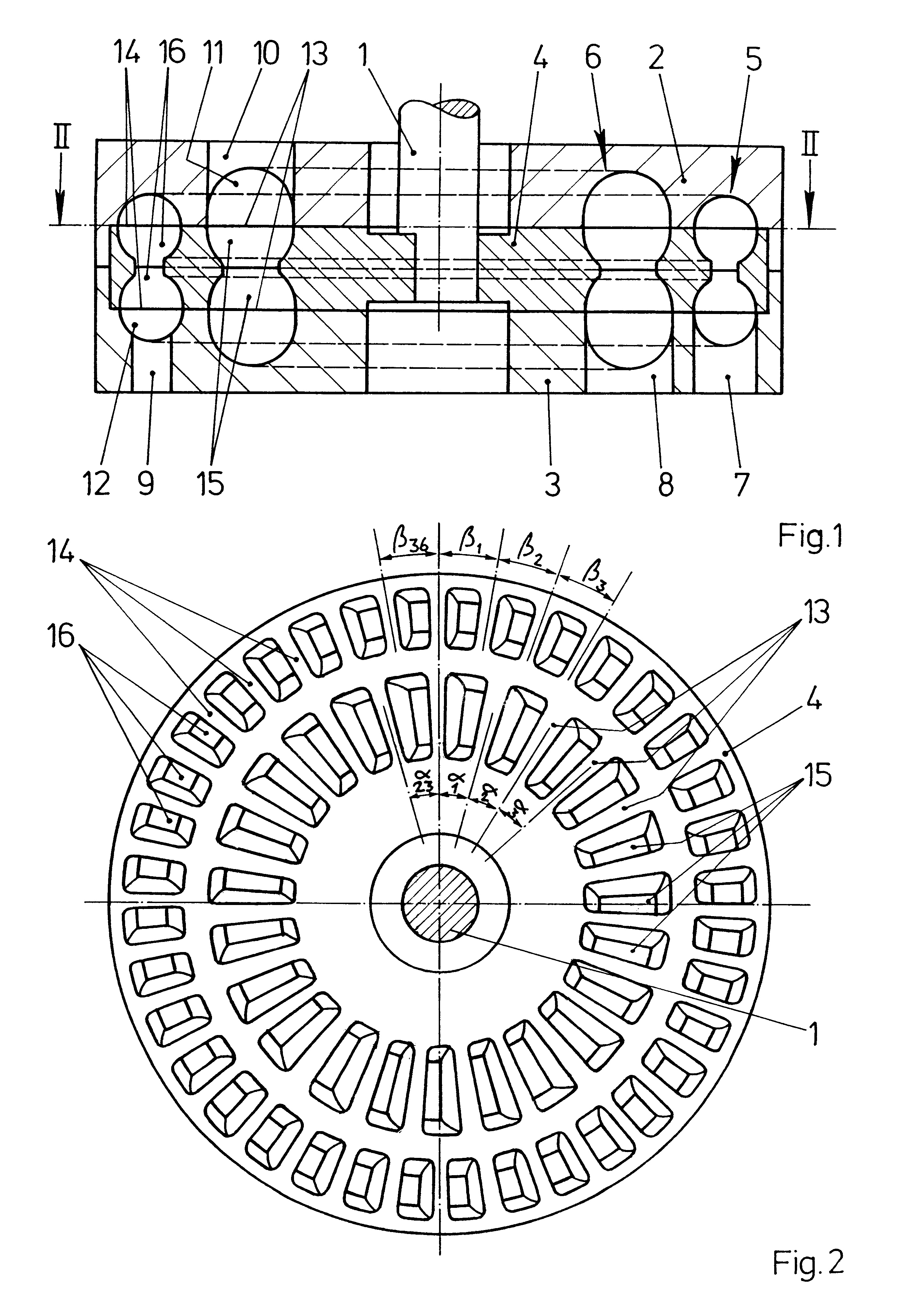
FIG. 1 is a sectional view through a feed pump designed as a side-channel pump. The feed pump includes an impeller 4 fastened on a shaft 1 and rotatable between two fixed housing parts 2, 3. The feed pump has two feed chambers 5, 6, one concentrically surrounding the other. The feed chambers 5, 6 respectively extend from an inlet channel 7, 8 as far as an outlet channel 9, 10. Furthermore, the feed chambers 5, 6 are respectively composed of feed channels 11, 12 arranged in the housing parts 2, 3 and of blade chambers 15, 16 arranged in the impeller 4. The blade chambers 15, 16 are delimited by moving blades 13, 14. Each of the blade chambers 15, 16 is arranged as a depression in one of the end faces of the impeller 4. Blade chambers 15 which are located on opposing sides of the impeller 4 and blade chambers 16 located on opposing sides of the impeller 4 are connected to one another. Rotation of the impeller 4 creates circulation flows leading from the inlet channels 7, 8 to the outl...


PUM


Abstract

A feed pump includes an impeller with two rings of guide blades delimiting blade chambers. The rings of guide blades concentrically surrounding one another and have different angular intervals between guide blades. The angular intervals between the guide blades of each ring vary within a range of values and ranges of values of each ring of guide blades is different to avoid the additions of noise emissions the feed pump consequently has noises which cause particularly little disturbance.

Description

1. Field of the InventionThe invention relates to a feed pump with at least one driven impeller rotating in a pump casing, wherein a plurality of rings of blade chambers are arranged on at least one end face of the impeller, feed channels are arranged opposite the rings of blade chambers in the wall of the pump casing, and guide blades delimit the blade chambers of the impeller.2. Description of the Related ArtFeed pumps with impellers having plural ring blade chambers are often used for feeding fuel out of a fuel tank in present-day motor vehicles and are known from practice. The known feed pump includes two rings of blade chambers, one concentrically surrounding the other, on a common impeller. When the impeller rotates, the fuel passes via an inlet channel first into a radially inner one of the feed channels and subsequently into a radially outer one of the feed channels. The pump consequently has two pumping stages.Furthermore, another known feed pump is made with two impellers,...

Claims


Application Information

Patent Timeline
Patent Type & Authority Patents(United States)
IPC IPC(8): F04D29/18F04D5/00F04D29/22F04D29/24
CPCF04D5/005F04D29/188F04D5/00
Inventor MARX, PETERWILHELM, HANS DIETERBARTH, HOLGER
Owner VITESCO TECH GERMANY GMBH
Why Eureka
Try Eureka