Vacuum-assisted laminator and methods of using the same

a technology of vacuum-assisted laminators and laminators, which is applied in the direction of mechanical working/deformation, manufacturing tools, chemical apparatuses and processes, etc., can solve the problems of large surface area, increased cost of film application, and use of film application, etc., and achieves high pressure

Inactive Publication Date: 2002-11-05
3M INNOVATIVE PROPERTIES CO
View PDF15 Cites 44 Cited by
  • Summary
  • Abstract
  • Description
  • Claims
  • Application Information

AI Technical Summary

Benefits of technology

The present invention provides apparatus and methods for laminating films to substrates where lamination pressure is generated at least partially by a vacuum drawn in a vacuum cavity. Advantages of the apparatus a

Problems solved by technology

These large surfaces require extensive time and labor for application of films.
This often adds more cost to the project that does the film itself.
Furthermore, many of these applications are on surfaces that contain compound-curved protrusions or indentations such as channels or rivets or other irregularities that increase application time and often produce wrinkles.
One problem in the art is that the application o

Method used


Image

  • Vacuum-assisted laminator and methods of using the same
  • Vacuum-assisted laminator and methods of using the same
  • Vacuum-assisted laminator and methods of using the same

Examples


Embodiment Construction

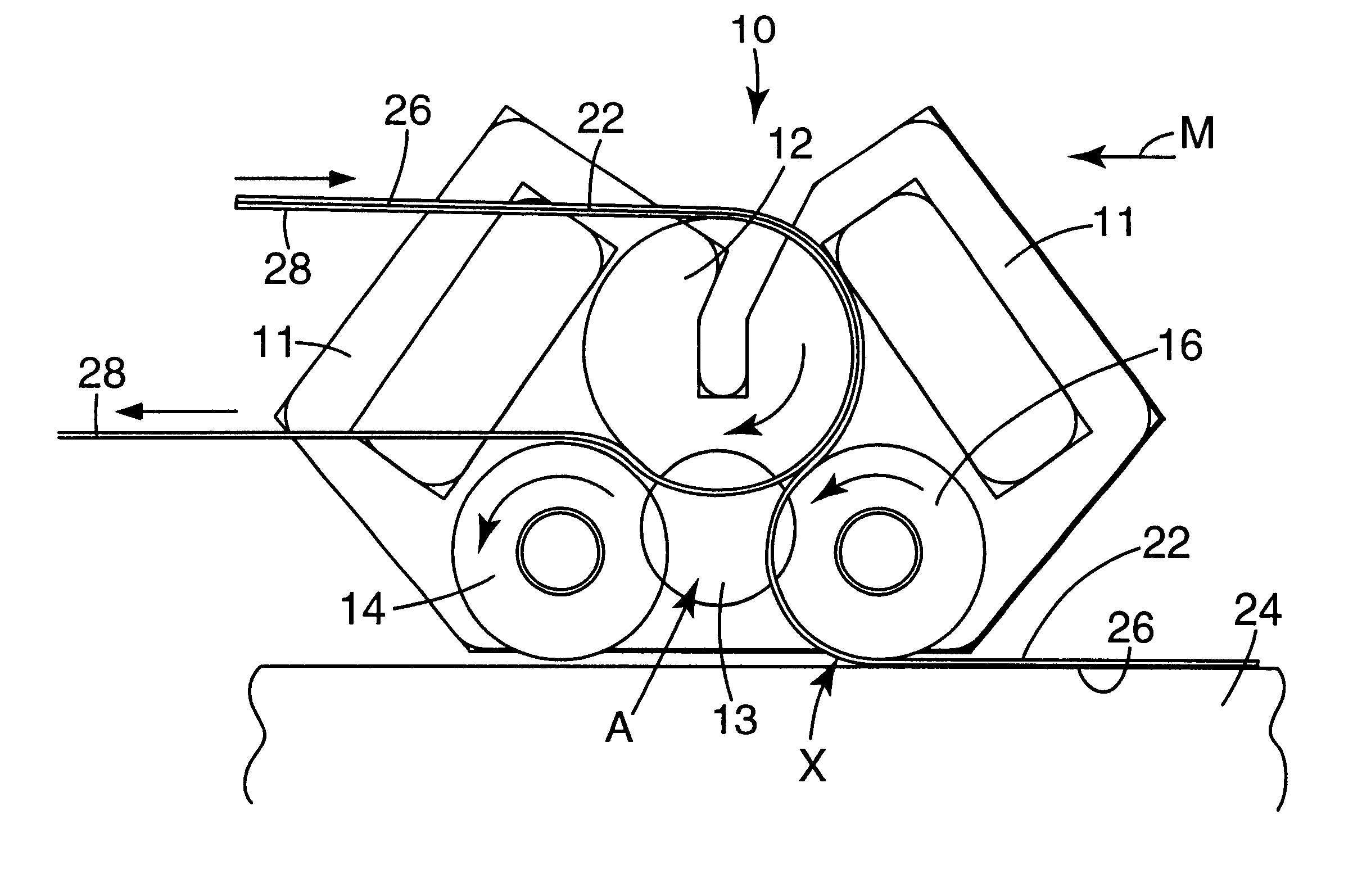
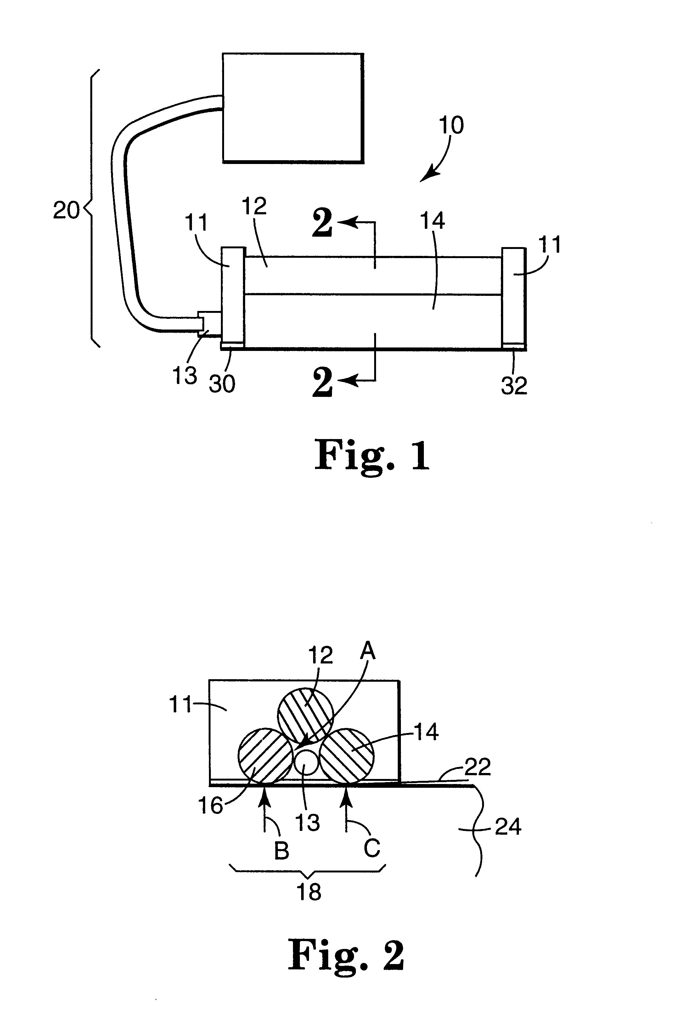
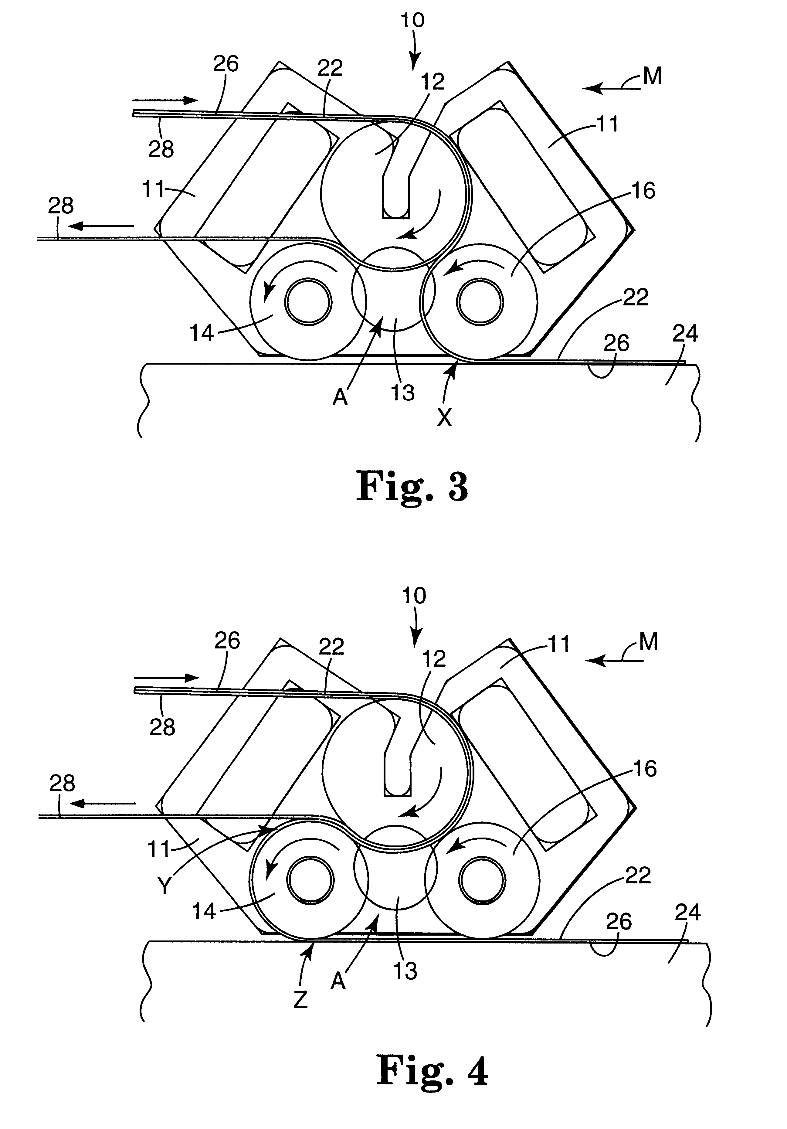
FIGS. 1 and 2 show one lamination apparatus 10 having a frame 11. At least one end of the frame 11 includes a vacuum port 13 in fluid communication with a vacuum cavity A formed in between the rolls 12, 14, and 16. The rolls 12, 14, and 16 combine to defined the vacuum cavity A and to provide lamination pressure on a film. The rolls 12, 14 and 16 are preferably circular and rotate about longitudinal axes extending through their centers. The longitudinal axes of the rolls are generally parallel to each other.

The lamination apparatus 10 may also include a vacuum or negative pressure source 20 that generates a partial vacuum (negative pressure) within the vacuum cavity A. That vacuum draws the outer rolls 14 and 16 against film 22 and the substrate 24 to provide the desired lamination pressure.

The substrate 24 on which the outer rolls 14 and 16 are mounted may be flat, or it may be curved such as, e.g., a roll. Furthermore, substrate 24 may be another film located on a flat or curved s...


PUM

PropertyMeasurementUnit
Lengthaaaaaaaaaa
Vacuumaaaaaaaaaa

Abstract

A vacuum-assisted lamination apparatus and methods of using the same to laminate a film to a substrate or two or more continuous webs together are disclosed. The apparatus includes a series of rolls and a partial vacuum source to provide pressure on a film or films.

Description

This invention concerns apparatus and methods for laminating films. More particularly, the present invention provides apparatus and methods using vacuum to generate a laminating force.BACKGROUND OF INVENTIONThe lamination of films often requires that pressure be supplied to force the film against a substrate to which it is to laminated. The substrate to which the film is to be laminated may be another film, a fabric, a structure (e.g., the side of vehicle, a wall, etc.) or any other object. The films are often coated with an adhesive to adhere the film to the substrate, but lamination of the adhesive-coated film under pressure often assists in providing a more secure bond between the film and the substrate. The use of pressure may also provide other advantages, e.g., reducing bubble formation, improving conformity, etc.Although it is desirable to use pressure when laminating a film to a substrate, it can be difficult to provide enough pressure to effectively influence the lamination...

Claims


Application Information

Patent Timeline
IPC IPC(8): B29C65/00B29C65/02B29L9/00
CPCB29C63/0078B29C66/82B32B37/1018B32B37/0053Y10T156/1741B32B2309/68B29C63/0056B29C63/0065B29C63/0091B29C65/4825B29C66/1122B29C66/45B29C66/81241B29C66/81264B29C66/83411B29C66/83413B29C66/83417B29K2995/007B29C65/52
Inventor STEELMAN, RONALD S.DAVID, JOHN R.
Owner 3M INNOVATIVE PROPERTIES CO
Why Eureka
Try Eureka