Hand operated belt sander

Inactive Publication Date: 2002-11-05
ROBERT BOSCH GMBH
View PDF4 Cites 15 Cited by
  • Summary
  • Abstract
  • Description
  • Claims
  • Application Information

AI Technical Summary

Problems solved by technology

Such a drive is heavy, expensive, and takes up a great dea

Method used


Image

  • Hand operated belt sander
  • Hand operated belt sander
  • Hand operated belt sander

Examples


Example

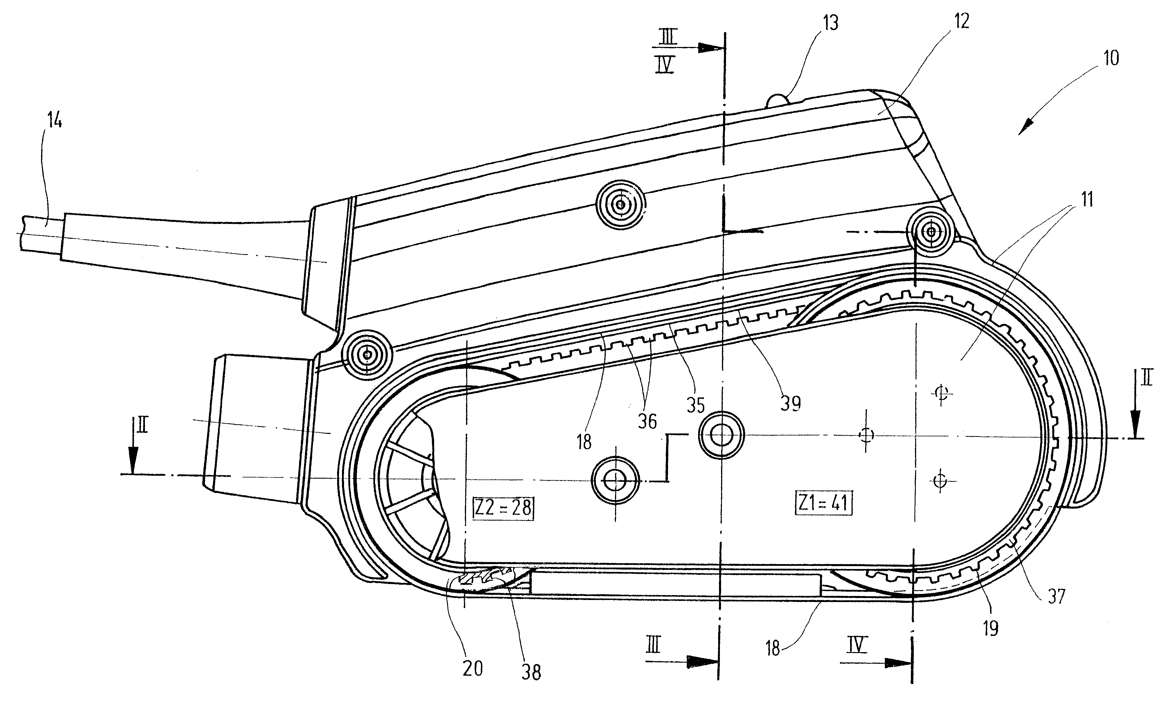
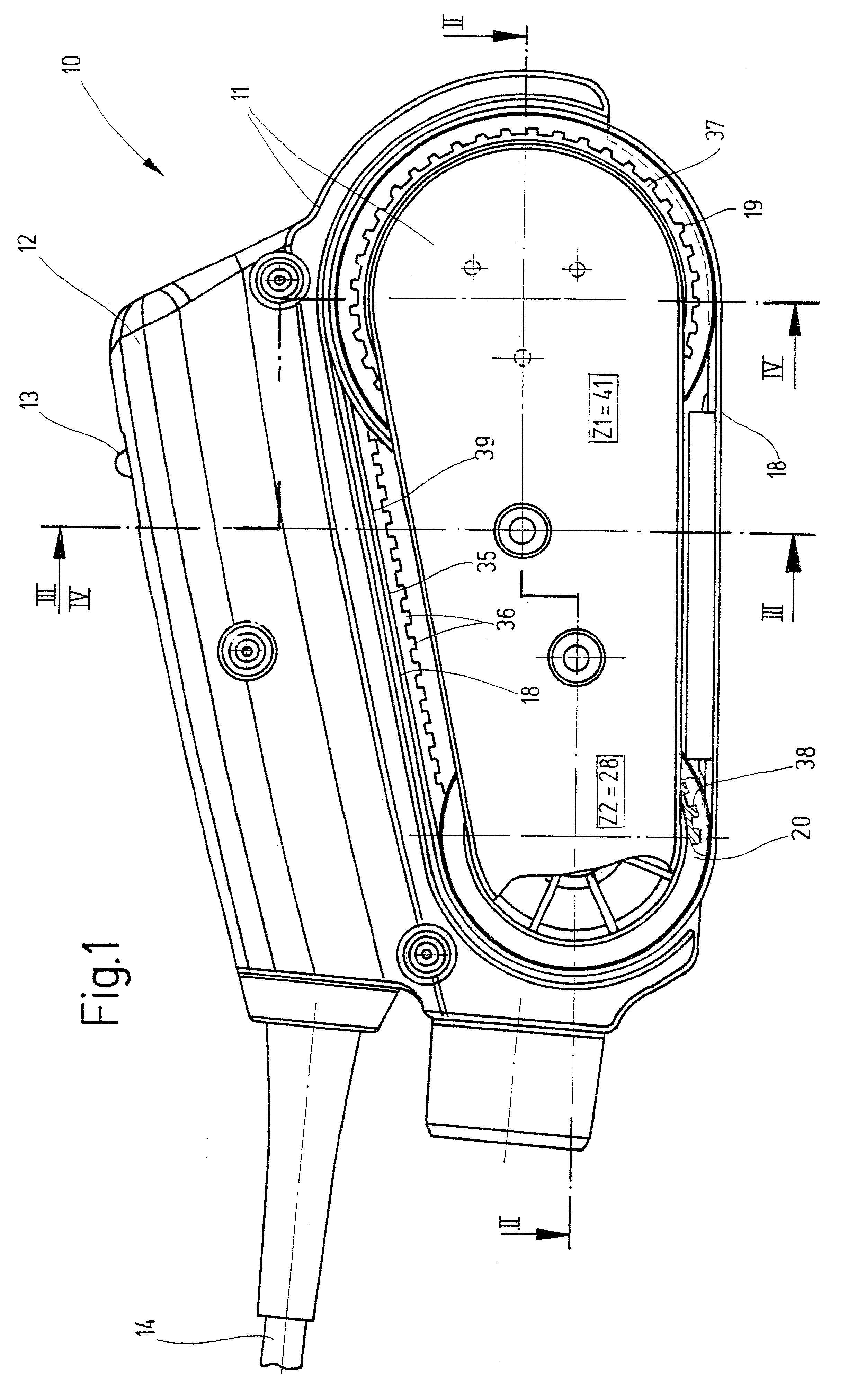
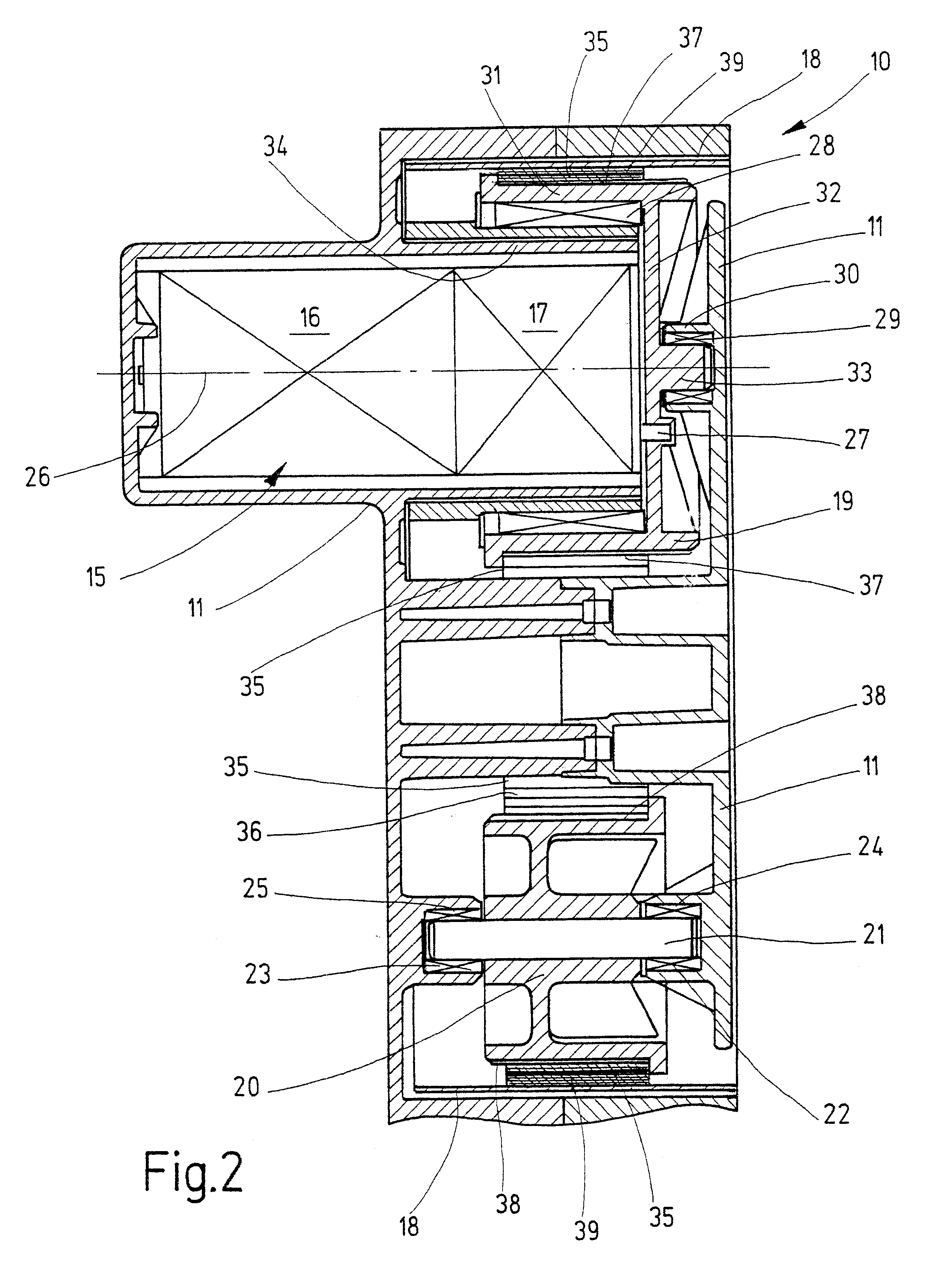
hand sand bander 10 is shown in the diagrams as an example of a hand band sanding machine comprising a housing 11 with handle 12 on the top side designed approximately in the shape of a strap. On the top side in the right-hand area in FIG. 1, the handle 12 contains a switch designed as a sliding switch 13, by way of which the electrical energy supplied by means of an electric cord 14 can be controlled, which serves to supply a drive--indicated in general with number 15--inside the housing 11. The drive 15 comprises an, in particular, electric motor 16 with gear 17 and serves to drive a sanding band 18--shown only diagrammatically--which can be driven in circulating fashion by way of a drive pulley 19 that can be driven in rotary fashion, and a return pulley 20 supported at a distance from it in rotatable fashion in the housing 11 and which can be driven by way of rotary operation of the drive pulley 19. The housing 11 represents a formation that is basically multipart and extends i...


PUM


Abstract

A hand band sander (10) with a housing (11) that contains a drive (15) for the sanding band (18) comprising a motor (16) with gear (17), which sanding band (18) can be driven in circulating fashion by way of a drive pulley (19) that can be driven in rotary fashion, and preferably by way of a return pulley (20), is smaller, easier to handle, and more reasonably priced due to the fact that the drive pulley (19) is arranged and supported coaxially to the drive (15) and is driven directly by the output of the gear (17).

Description

RELATED ARTThe invention concerns a hand band sander according to the preamble of Claim 1.Hand band sanders according to the general class in the form of hand band sanding machines are known that are designed as hand-operated devices of considerable size and considerable weight and therefore have two handles located some distance apart and that must be held by both handles to be used. To realize desired optimal band speeds of the sanding band, universal motors are run at high speeds, whereby the speed is then geared down by way of a multistage gear, e.g., in the form of a spur-toothed wheel or angular gear in combination with a toothed belt gear. The drive of the motor is therefore usually controlled by way of a pinion on a toothed wheel supported at a distance from it, both of which are connected in gear-like fashion by way of a toothed belt. The toothed wheel itself drives a spur gear, on the driven shaft of which the drive pulley is situated, which is therefore located at a dista...

Claims


Application Information

Patent Timeline
IPC IPC(8): B24B21/00B24B21/20B24B23/06B24B23/00
CPCB24B21/20B24B23/06
Inventor WUENSCH, STEFFEN
Owner ROBERT BOSCH GMBH
Why Eureka
Try Eureka