Ejector cycle system with critical refrigerant pressure

a technology of ejector cycle and critical refrigerant pressure, which is applied in the operation mode of machines, refrigeration components, light and heating equipment, etc., can solve the problems of reducing the coefficient of refrigerant cycle performance and increasing the power needed for compressor operation

Inactive Publication Date: 2002-11-12
DENSO CORP
View PDF16 Cites 141 Cited by
  • Summary
  • Abstract
  • Description
  • Claims
  • Application Information

AI Technical Summary

Benefits of technology

According to the present invention, an ejector cycle system includes a compressor for sucking and compressing refrigerant, a radiator for cooling refrigerant discharged from the compressor, an evaporator in which refrigerant is evaporated by absorbing heat, an ejector which decompresses and expands refrigerant from the radiator to suck gas refrigerant evaporated in the evaporator and converts an expansion energy to a pressure energy to increase a refrigerant pressure to be sucked into the compressor, and a gas-liquid separator for storing refrigerant and for separating refrigerant into gas refrigerant and liquid refrigerant. In the refrigerant cycle system, a refrigerant pressure before being decompressed in the ejector is equal to or higher than the critical pressure of refrigerant. When refrigerant is used in a super-critical area (trans-critical area), a ratio of a specific enthalpy difference to a pressure change (.DELTA.P) becomes larger, and a pressure difference during the decompression and expansion becomes larger, as compared with a case using freon as refrigerant. Thus, in the present invention, the expansion energy is sufficiently recovered during the decompression. Further, in the ejector, the pressure of refrigerant discharged from the ejector is increased from a middle pressure higher than a pressure within the evaporator to a pressure lower than the critical pressure. Therefore, consumption power of the compressor can be reduced. In the super-critical area of refrigerant, because a density of gas refrigerant is approximately equal to that of liquid refrigerant, refrigerant decompressed and expanded in the ejector has approximately equal speed in both gas refrigerant and liquid refrigerant. For example, when carbon dioxide is used as refrigerant, an ejector efficiency is increased approximately twice, as compared with a case where freon is used as refrigerant. As a result, in the ejector cycle of the present invention, because the refrigerant pressure before being decompressed in the ejector is equal to or higher than the critical pressure of refrigerant, the coefficient of performance of the ejector cycle system can be improved.
Preferably, the gas-liquid separator is disposed so that gas refrigerant in the gas-liquid separator is supplied toward a suction side of the compressor and liquid refrigerant in the gas-liquid separator is supplied to the evaporator, and the ejector cycle system further includes a heating unit which heats refrigerant sucked into the compressor. Therefore, temperature of refrigerant sucked into the compressor can be increased, the refrigerant temperature discharged from the compressor is also increased, and the radiator capacity and the efficiency of the ejector cycle system can be improved.
Further, a control valve is disposed in a refrigerant passage of the ejector cycle system so that refrigerant pressure before being decompressed in the ejector is equal to or higher the critical pressure of refrigerant. Therefore, the ejector cycle system operates while the ejector efficiency is improved. preferably, the control valve and the ejector are integrated. Therefore, the structure of the ejector cycle system can be made simple. More preferably, the ejector includes a nozzle in which a pressure energy of high-pressure refrigerant flowing from the radiator is converted to a speed energy so that refrigerant is decompressed and expanded, and a pressure increasing portion in which the speed energy is converted to the pressure energy so that the pressure of refrigerant is increased while refrigerant discharged from the nozzle and refrigerant sucked from the evaporator are mixed. The control valve can be integrated with the nozzle of the ejector.

Problems solved by technology

However, in this case, because it is necessary to increase high-pressure side refrigerant pressure to be equal to or higher than the critical pressure, a necessary power for operating a compressor becomes larger, and coefficient of performance of the refrigerant cycle is decreased.

Method used


Image

  • Ejector cycle system with critical refrigerant pressure
  • Ejector cycle system with critical refrigerant pressure
  • Ejector cycle system with critical refrigerant pressure

Examples


first embodiment

A first preferred embodiment of the present invention will be now described with reference to FIGS. 1-3. In the first embodiment, an ejector cycle system of the present invention is typically applied to a reference cycle using carbon dioxide as refrigerant, for a vehicle air conditioner.

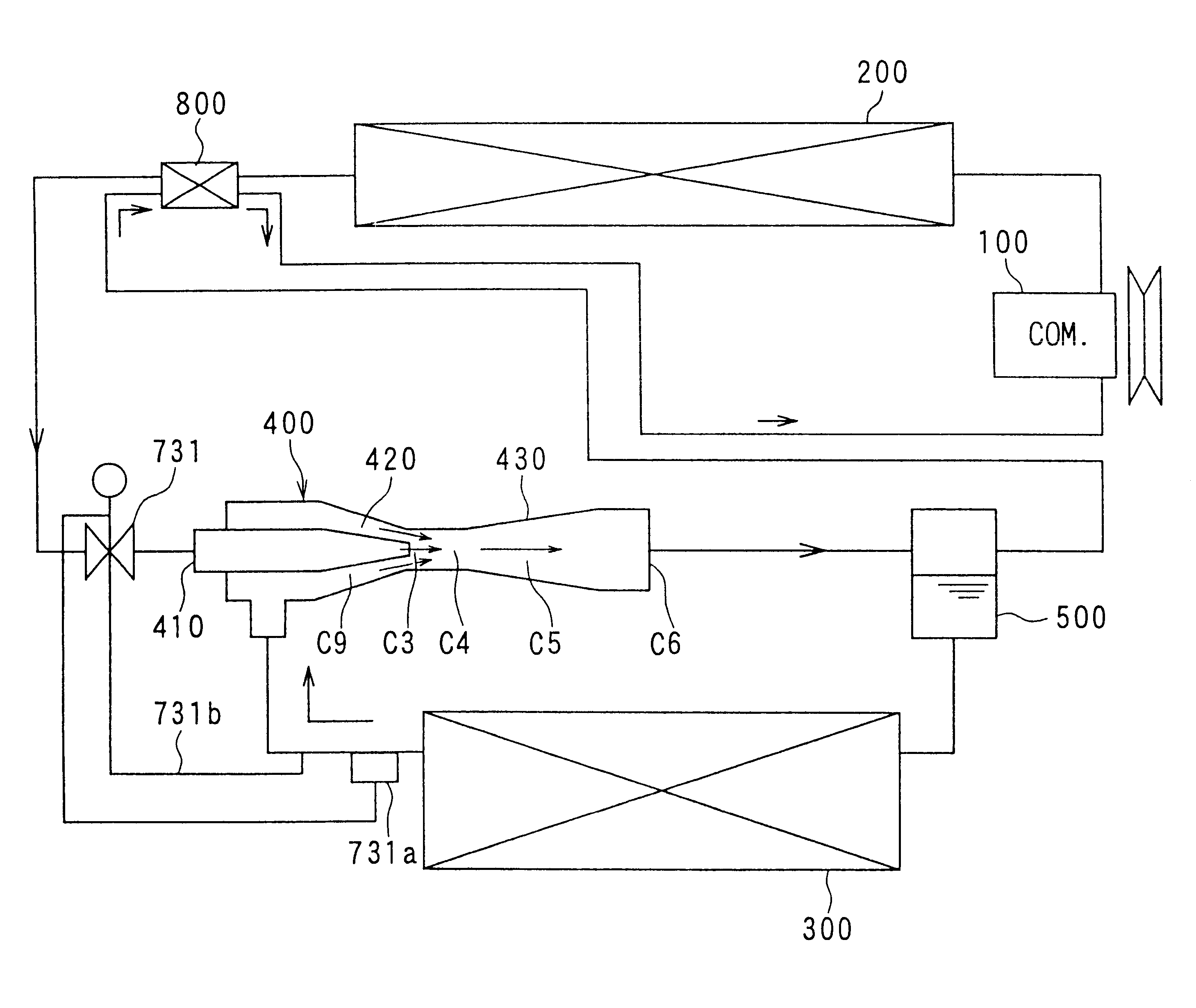
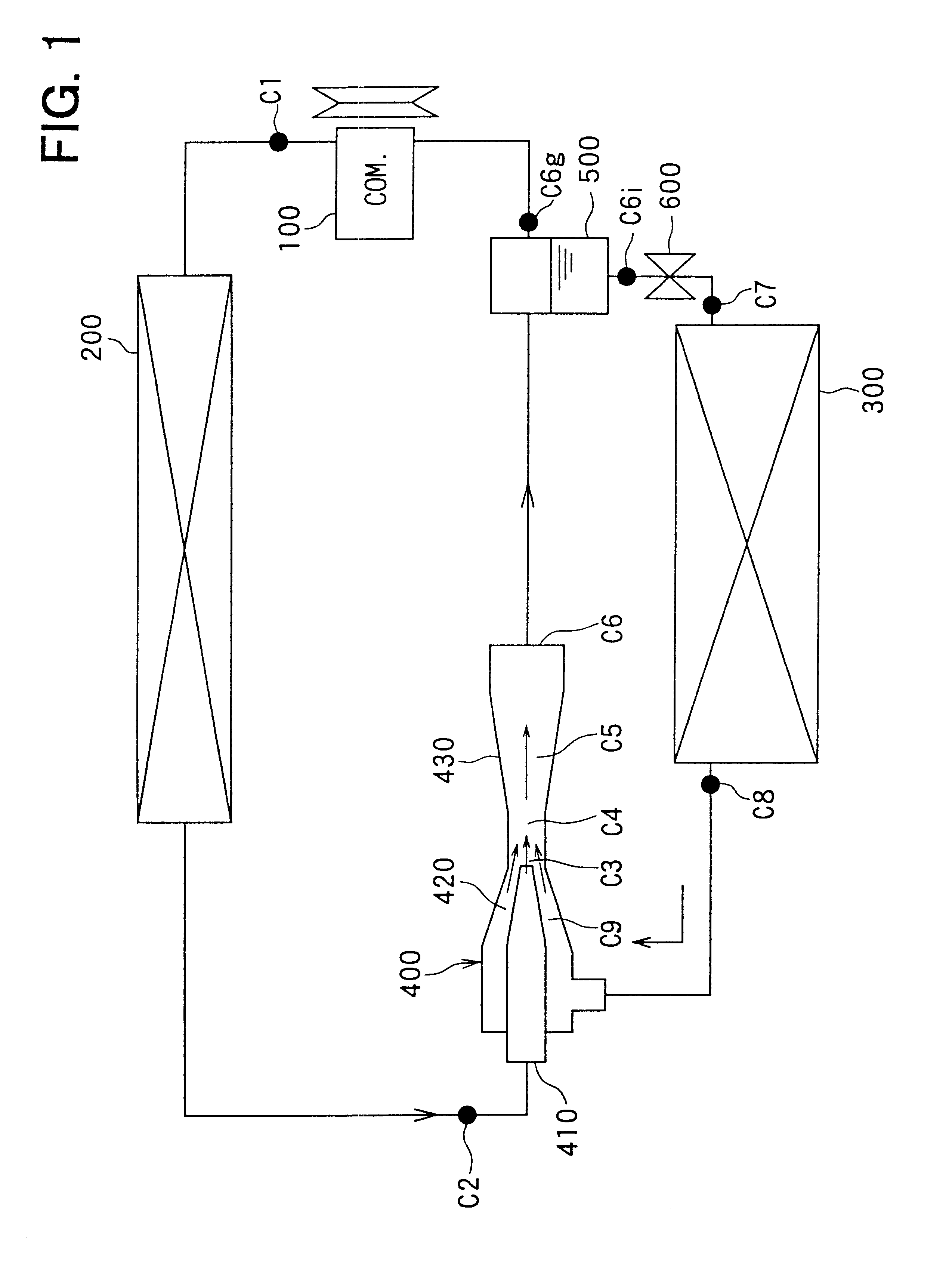
As shown in FIG. 1, a compressor 100 which sucks and compresses refrigerant using a driving force from a driving source such as a vehicle engine is disposed in the ejector cycle system. A radiator 200 (gas cooler) is disposed so that refrigerant discharged from the compressor 100 is heat-exchanged with outside air outside a passenger compartment and is cooled by outside air.

An evaporator 300 is disposed in the ejector cycle system so that air blown into the passenger compartment and liquid refrigerant flowing through the evaporator 300 are heat-exchanged. In the evaporator 300, cooling capacity can be obtained by the evaporation of liquid refrigerant. Refrigerant from the radiator 200 is decompressed...

second embodiment

A second preferred embodiment of the present invention will be now described with reference to FIG. 4. In the second embodiment, as shown in FIG. 4, a second decompression unit 710, which reduces the refrigerant pressure increased in the diffuser 430 of the ejector 400, is disposed at a downstream side of the ejector 400. Therefore, the increased pressure of refrigerant in the diffuser 430 of the ejector 400 is decompressed in the second decompression unit 710 to have a predetermined decompressed pressure lower than the critical pressure. Thereafter, refrigerant having the predetermined decompressed pressure lower than the critical pressure flows into the gas-liquid separator 500 to be sufficiently separated into gas refrigerant and liquid refrigerant.

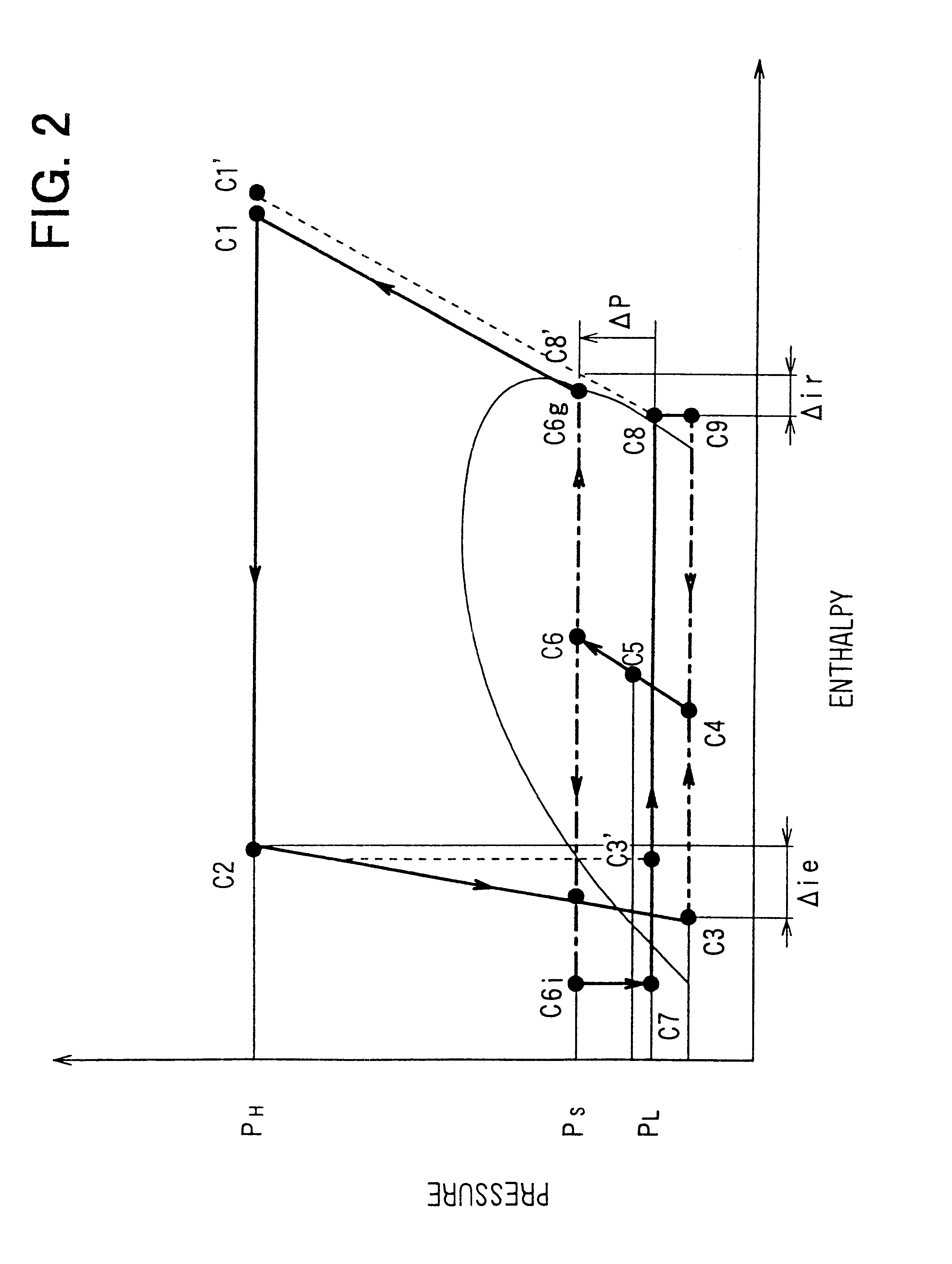
In the ejector cycle system using carbon dioxide as refrigerant, because the high-pressure side refrigerant pressure is equal to or higher than the super-critical pressure (trans-critical pressure), the refrigerant pressure discharged ...

fourth embodiment

liquid refrigerant to be supplied to the evaporator 300 is separated and extracted from refrigerant before being discharged from the ejector 400. Therefore, as shown by the solid line in FIG. 8, even when the suction pressure increased amount .DELTA.P becomes larger, a pressure increased amount .DELTA.Pe of liquid refrigerant flowing from the gas-liquid separator 500 can be made smaller than the suction pressure increased amount .DELTA.P.

Accordingly, it can prevent the specific enthalpy of refrigerant at the inlet of the evaporator 300 from being larger, and the specific enthalpy difference .DELTA.he between the refrigerant inlet and the refrigerant outlet of the evaporator 300 can be made larger than the specific enthalpy difference .DELTA.h. As a result, the cooling capacity Qe generated by the evaporator 300 can be increased.

FIG. 9 shows a simulation result showing a relationship between a refrigerant flow speed (relative speed Vgi / Vgno) from the refrigerant outlet of the nozzle ...


PUM


Abstract

In an ejector cycle system using carbon dioxide as refrigerant, an ejector decompresses and expands refrigerant from a radiator to suck gas refrigerant evaporated in an evaporator, and converts an expansion energy to a pressure energy to increase a refrigerant pressure to be sucked into a compressor. Because refrigerant is decompressed and expanded in a super-critical area, a pressure difference during the decompression operation becomes larger, and a specific enthalpy difference becomes larger. Accordingly, energy converting efficiency in the ejector becomes higher, and efficiency of the ejector cycle system is improved.

Description

This application is related to Japanese Patent Applications No. 2000-77827 filed on Mar. 15, 2000, No. 2000-237344 filed on Aug. 4, 2000, No. 2000-273585 filed on Sep. 8, 2000, No. 2000-387618 filed on Dec. 20, 2000, and No. 2001-5196 filed on Jan. 12, 2001, the contents of which are hereby incorporated by reference.1. Field of the InventionThe present invention relates to an ejector cycle system with a high-pressure side refrigerant pressure equal to or higher than the critical pressure of refrigerant. The ejector cycle system has an ejector in which high-pressure side refrigerant is decompressed and expanded so that gas refrigerant evaporated in an evaporator is sucked therein, and a refrigerant pressure sucked into a compressor is increased by converting an expansion energy to a pressure energy.2. Description of Related ArtIn recent years, instead of freon refrigerant, the other refrigerant is used in a vapor compression refrigerant cycle. For example, U.S. Pat. No. 5,245,836 des...

Claims


Application Information

Patent Timeline
Patent Type & Authority Patents(United States)
IPC IPC(8): F25B41/00F25B1/06F25B1/08F25B9/00F25B29/00F25B40/00F25B41/06
CPCF25B1/08F25B9/008F25B41/00F25B29/003F25B40/00F25B2309/061F25B2339/047F25B2341/0011F25B2341/0012F25B2341/0013F25B2341/063F25B2400/23F25B2500/01F25B2500/18F25B2600/025F25B2600/0253F25B2600/17F25B2700/21174F25B2700/21175Y02B30/741B60H2001/3298
Inventor TAKEUCHI, HIROTSUGUMAKIDA, KAZUHISAKUME, YOSHITAKAISHIKAWA, HIROSHIIRITANI, KUNIONOMURA, SATOSHISAKAKIBARA, HISAYOSHIIKEGAMI, MAKOTO
Owner DENSO CORP
Why Eureka
Try Eureka