
Jogger member, system and method for mounting jogger members and female and male blanking dies provided therewith

a technology of joggers and blanking dies, which is applied in the field of automatic die cutting apparatuses, can solve the problems of affecting the overall cost of production and price of box blanks, affecting the capacity and productivity of box blanks, and the problem of not being satisfactorily solved

Inactive Publication Date: 2002-11-12
SANDFORD PETER E
View PDF36 Cites 40 Cited by
  • Summary
  • Abstract
  • Description
  • Claims
  • Application Information

AI Technical Summary

Benefits of technology

The jogger members are now accurately positioned around the upper perimeter of the universal press frame. Some or all of the jogger members may have been previously placed around the inner perimeter of the universal press frame before the template is secured therein. If not, all the jogger members are placed at this time. In any event, jogger members which are selectively disposed along the interior perimeter of the rectangular framework of the universal press frame are adjusted to abut selected perimetrical edges of the lasered template. In this way, the jogger members are thereby accurately positioned.
If the back trim of the die-cut sheet of cardboard containing the plurality of cartons has been removed by the stripper, the jogger members are adjusted to abut the back of the layered template. If the side trim has been removed of the die-cut and blanked sheet of cardboard containing the plurality of cartons has been removed by the stripper, side rails are inserted into slots in the side jogger members, or alternatively, in special side support brackets, and are secured therein with lock-down bolts. This provides support for the side edges of the blanked sheet of cardboard.

Problems solved by technology

This, of course, resulted in diminished capacity and productivity and affected the overall cost of production and price of the box blanks.
While many of the above patents alluded to the solving of the problem of aligning the male blanking die with the female blanking die, with the die-cut carton blanks then being pushed through the female blanking die onto a stack of cartons below, in practice, such problem has not yet been satisfactorily solved.

Method used


Image

  • Jogger member, system and method for mounting jogger members and female and male blanking dies provided therewith
  • Jogger member, system and method for mounting jogger members and female and male blanking dies provided therewith
  • Jogger member, system and method for mounting jogger members and female and male blanking dies provided therewith

Examples


Embodiment Construction

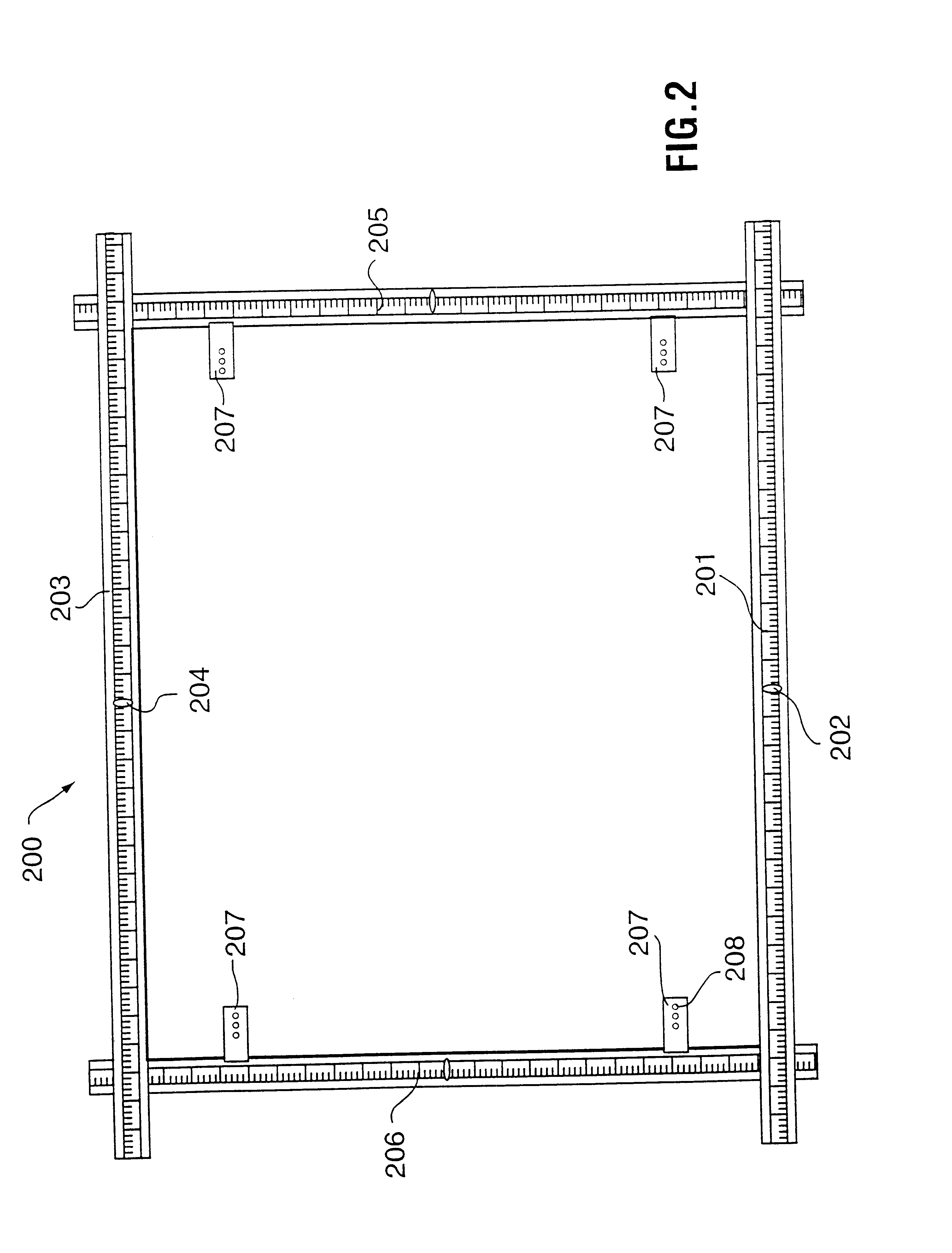
(i) Description of FIG. 2

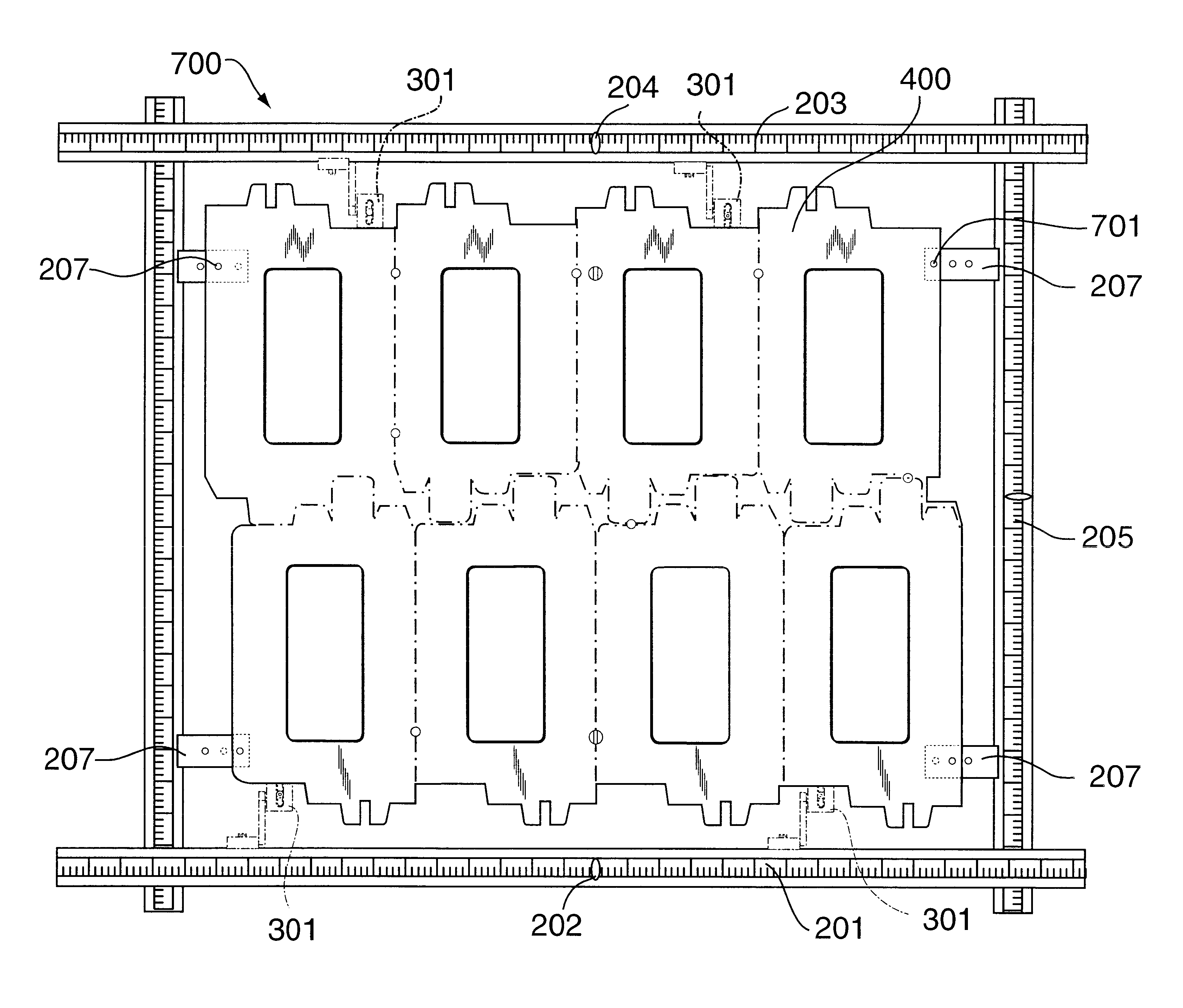
FIG. 2 shows a first step in the production of the female blanking die of one embodiment of the present invention. Shown are a universal press frame 200 constituted by a front rail 201, a rear rail 203, and two opposed side rails 205, 206. Opposed side rails 205, 206 are slidable transversally with respect to front rail 201 and rear rail 204, thereby to adjust the size of the rectangular size of the universal press frame. The front rail 201 is provided with a centre datum 202, and the rear rail is likewise provided with a centre datum 204. A plurality of support brackets, namely four brackets 207 are secured to the universal press frame, i.e., two brackets 207 are secured to side rail 205 and two brackets 207 secured to side rail 206. Each bracket 207 is provided with a plurality, e.g., three tapped apertures, for a purpose to be described hereinafter.

(ii) Description of FIG. 3

FIG. 3 shows a second step in the production of the female blanking die of one emb...


PUM

PropertyMeasurementUnit
perimeteraaaaaaaaaa
shapeaaaaaaaaaa
distanceaaaaaaaaaa

Abstract

A female blanking die for a die cutting machine for die cutting and / or blanking a carton blank, as well as a male blanking die / female blanking die combination, and methods of producing them, and elements constituting essential integers thereof, are all provided herein. The male blanking die / female blanking die combination includes a specifically-configured male stripping die. Such male stripping die includes a template having a particularly-specified perimeter, the template including a plurality of foam plastic pads which are removably secured to the undersurface of the template, the template being accurately secured at a predetermined position to the underface of a movable upper plate of the blanking station of the die cutting machine. The male blanking die / female blanking die combination also includes a specifically-configured female blanking die. Such female stripping die includes a rectangular framework and a plurality of grid support members, each grid support member having a slot across its upper face, the grid support members being selectively disposed along the internal perimeter of the rectangular framework. A grid is provided comprising a plurality of intersecting rails, the pattern of the intersecting rails having a predefined shape. The grid is disposed within the slots atop the grid support members. A plurality of jogger members are provided which are selectively disposed along the internal perimeter of the rectangular framework, each jogging member having a particularly-recited structure. The plurality of jogger members are oriented along the internal perimeter of the rectangular framework in a particularly-recited way. The female blanking die is accurately secured at a predetermined position atop a lower fixed plate of the blanking station of the die cutting machine. The male blanking die and the female blanking die are accurately aligned to cooperate to press and separate the carton blanks from a web holding them together, and to force the separated cartons through aligned openings in the female blanking die.

Description

(i) Field of the InventionThe present invention relates generally to an improvement in apparatus for the automatic die cutting of blanks primarily for making formable paperboard containers. In particular, it relates to improvements in the blanking operation to assist in the removal of the carton blanks, after the stripping operation, in an efficient manner.(ii) Description of the Prior ArtWith the advent of many different sizes, shapes and configurations of cardboard or similar type containers, it is well-known in the art to die-cut, strip and blank cardboard box blanks using an automatic sequential press or die cutting machine. By automating the process and by using computer-aided technology, it is now possible to confiture die-cut blanks in a limitless number of dimensions and specifications and, as well, to lay-out any number of blanks on a single sheet of cardboard while automatically cutting, stripping and blanking the sheets with little or no human operator intervention. One t...

Claims


Application Information

Patent Timeline
Patent Type & Authority Patents(United States)
IPC IPC(8): B26D7/18B31B50/14
CPCB26D7/1818B26D2007/189Y10T83/9437Y10T83/2209Y10T83/731
Inventor SANDFORD, PETER E.
Owner SANDFORD PETER E
Learn More