Card mounted with circuit chip and circuit chip module

Inactive Publication Date: 2002-11-12
ROHM CO LTD
View PDF8 Cites 49 Cited by
  • Summary
  • Abstract
  • Description
  • Claims
  • Application Information

AI Technical Summary

Benefits of technology

An object of the present invention is to provide a circuit chip mounted card and the like

Problems solved by technology

This means that the strain is extremely great when IC card 2 is subjected to a great bending force and the like.
This deformation causes a crack in IC chip 8 to degrade the function as an IC card.
Thus, there was a

Method used


Image

  • Card mounted with circuit chip and circuit chip module
  • Card mounted with circuit chip and circuit chip module
  • Card mounted with circuit chip and circuit chip module

Examples


Example

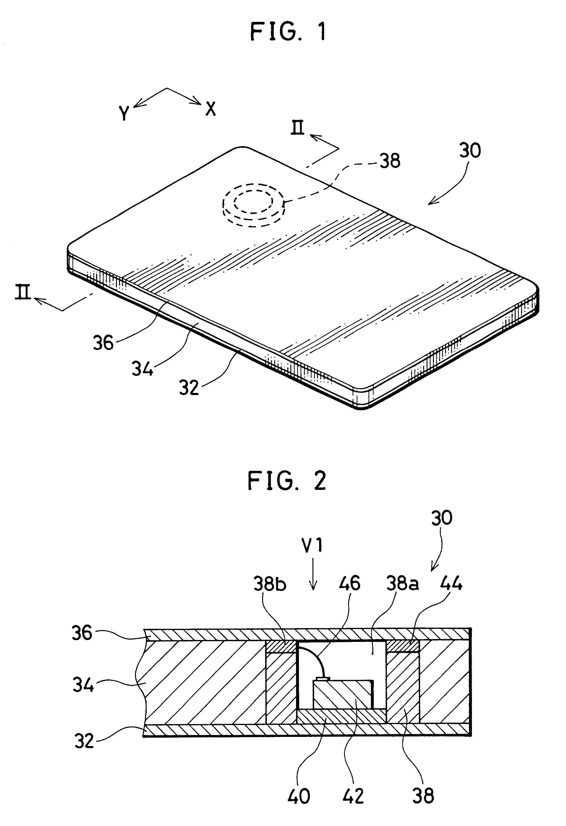
FIG. 1 shows an appearance of a non-contact type IC card 30 as a circuit chip mounted card according to an embodiment of the present invention. IC card 30 is a one-coil type IC card used in the automatic examination for a ski lift at skiing grounds and railways, automatic sorter of parcels, and the like.

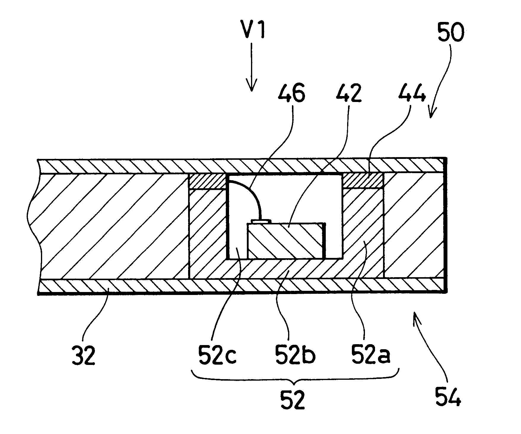
FIG. 2 is a sectional view taken along line II--II of FIG. 1. IC card 30 has a structure of sequential layers of a surface layer member 32 which is the first substrate, a core member 34, and surface layer member 36 which is the second substrate. Synthetic resin such as vinyl chloride, PET (polyethylene terephthalate) and the like are used for surface layer members 32 and 36. Core member 34 is formed of synthetic resin.

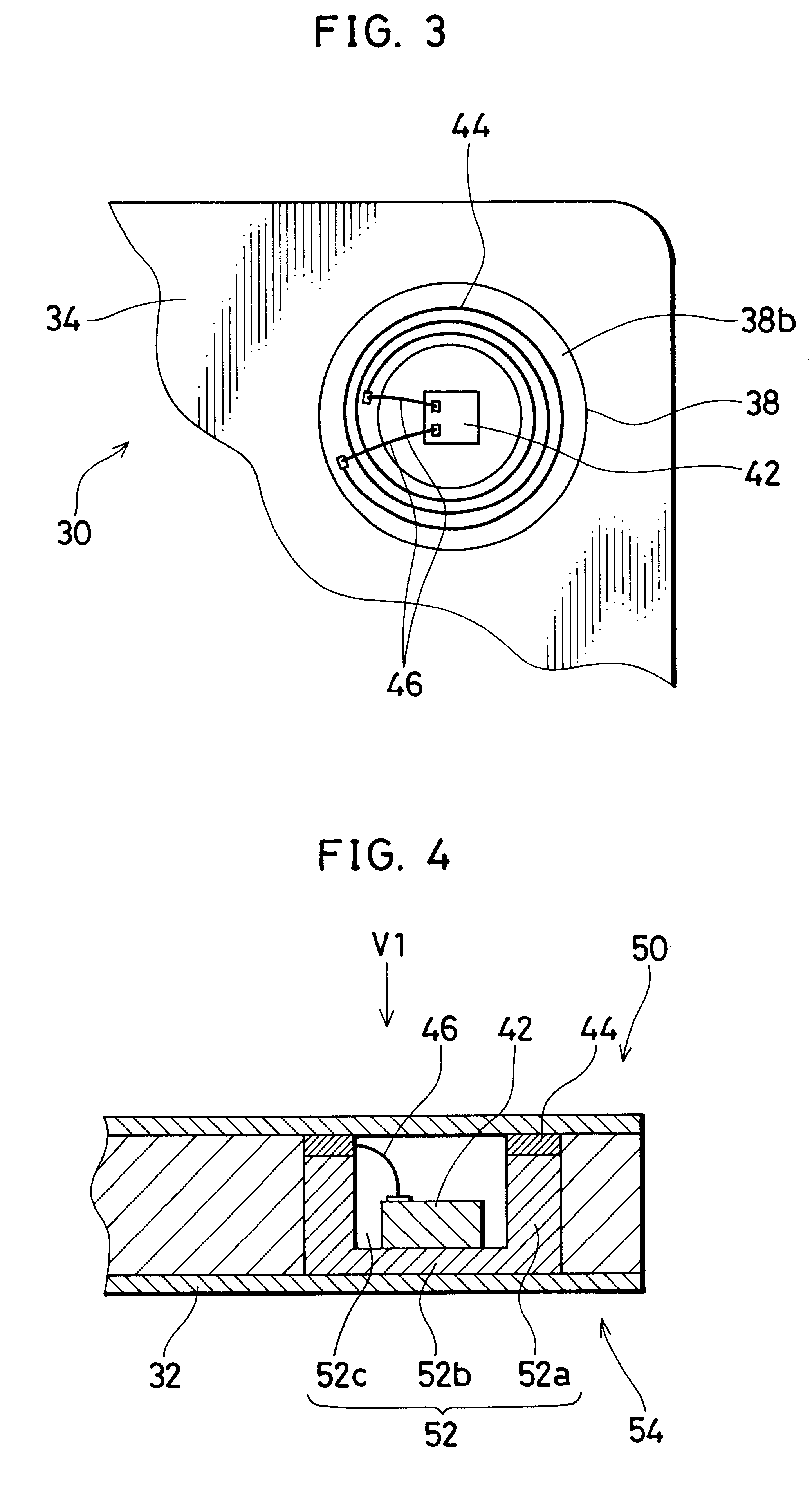
A ceramic frame 38 is embedded in the layer formed of core member 34. Ceramic frame 38 is formed of ceramic in a cylindrical configuration. Ceramic frame 38 corresponds to the frame of a reinforcing body. In the present embodiment, the reinforcing body is formed only of...


PUM


Abstract

A highly rigid ceramic frame (38) is embedded in a layer of a core member (34). An IC chip (42) is held inside (38a) via an elastic member (40). IC chip 42 arranged inside (38a) will not be greatly deformed even when a strong bending, torsional, or pressing force is applied to the IC card (30). An impact, when exerted on the IC card (30), will not be directly conveyed to the IC chip (42). A coil (44) formed by printing and the like is provided at an upper end face (38b) of the ceramic frame (38). The coil (44) is connected to the IC chip (42) by a wire (46). By forming the IC chip (42), the ceramic frame (38) and the coil (44) integrally in advance, the workability in fabrication is improved. Therefore, a circuit chip mounted card of high reliability and low fabrication cost can be provided.

Description

The present invention relates to a card mounted with a circuit chip, and a circuit chip module. Particularly, the present invention relates to a circuit chip mounted card and a circuit chip module realizing improvement of reliability and reduction in fabrication cost.A non-contact type IC card is used in automatic examination for lifts in skiing grounds and railroads, automatic sorting of parcels, and the like. An example of a conventional non-contact IC card is shown in FIG. 7. An IC card 2 shown in FIG. 7 is a one-coil type IC card, including a coil 4 used as an antenna, capacitors C1 and C2, and an IC chip 8.Capacitors C1 and C2 and IC chip 8 are mounted on a film-like synthetic resin substrate. The substrate mounted with capacitors C1 and C2 and IC chip 8 is referred to as a tab (tape automated bonding) 10.FIG. 8A is a sectional view of IC card 2. A core member 12 of synthetic resin is sandwiched by a pair of surface layer members 14 and 16. Tab 10 mounted with capacitors C1, C2...

Claims


Application Information

Patent Timeline
IPC IPC(8): G06K19/077G06K19/07B42D15/10
CPCG06K19/07728G06K19/07745G06K19/07747G06K19/07749G06K19/0775G06K19/07779G06K19/07783H01L2224/48091H01L2924/01039H01L2924/19041H01L2924/3011H01L2924/00014
Inventor IKEFUJI, YOSHIHIROCHIMURA, SHIGEMIKOMURO, TOYOKAZU
Owner ROHM CO LTD
Why Eureka
Try Eureka