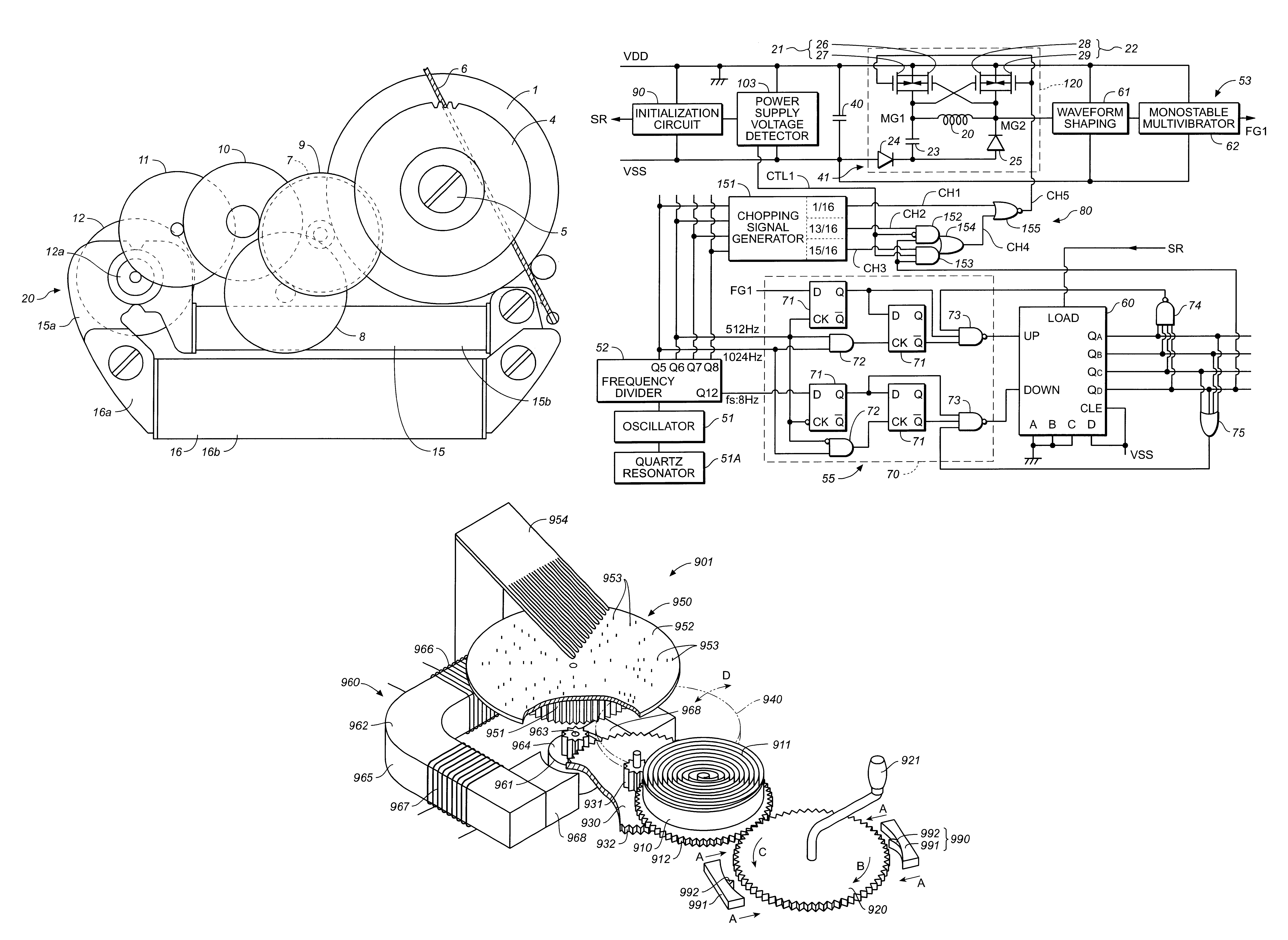
Electronic device with variable chopping signal and duty ratio selection for strong braking

a technology of electronic devices and duty ratios, applied in the direction of dynamo-electric converter control, horology, instruments, etc., can solve the problems of electronic control mechanical clocks, limitation in suppressing the reduction of electric power, and electric power generation reduction, so as to achieve simple configuration and reduce cost

Inactive Publication Date: 2002-11-19
SEIKO EPSON CORP
View PDF22 Cites 20 Cited by
  • Summary
  • Abstract
  • Description
  • Claims
  • Application Information

AI Technical Summary

Benefits of technology

The present embodiment also has the advantages described above in (1)-(11) with reference to the first embodiment, as well as the advantage described below.
(13) The switching of the chopping signal used in the strong braking mode is performed by a simple circuit...

Problems solved by technology

However, in the technique of Japanese Examined Patent Publication No. 7-119812, a reduction in electric power generated by the electric power generator occurs when the electric power generator is braked, and thus there is a limitation in suppressing the reduction in the electric power when the braking torque is increased.
This problem occurs not only in electronically controlled mechanical clocks, but also in other various electronic devices, such as music boxes, metronomes, and electric shavers, each of which include a part rotated by a mechanical energy source such as a spring or...

Method used


Image

  • Electronic device with variable chopping signal and duty ratio selection for strong braking
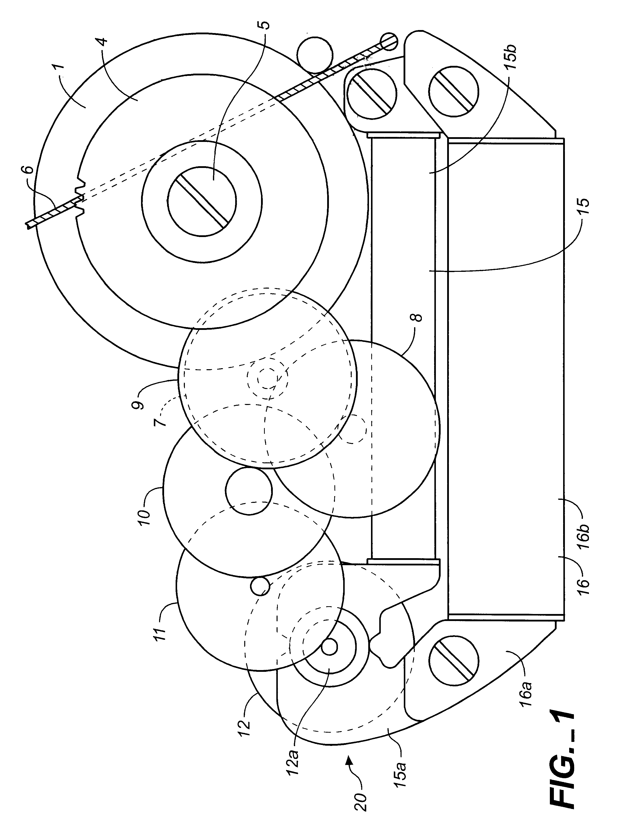
  • Electronic device with variable chopping signal and duty ratio selection for strong braking
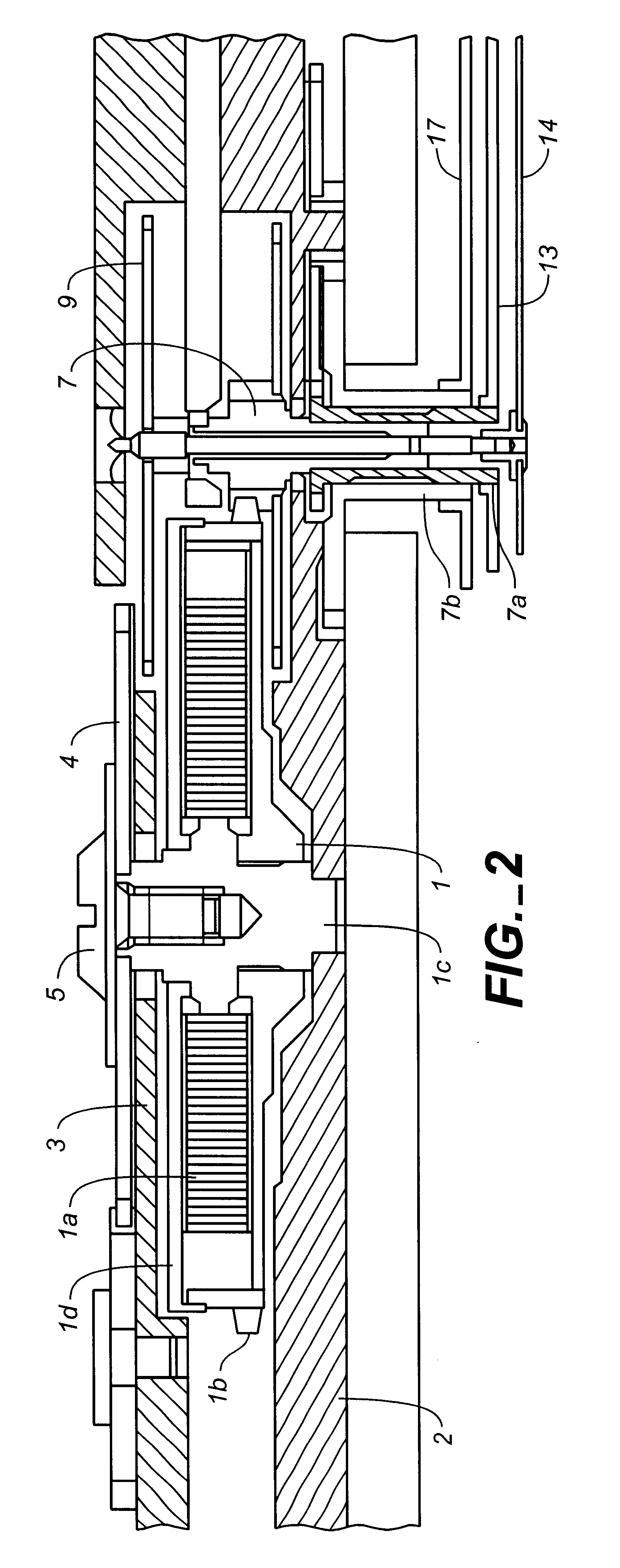
  • Electronic device with variable chopping signal and duty ratio selection for strong braking

Examples


Embodiment Construction

The effects of the chopping technique have been experimentally investigated as follows.

Experiments were performed using a chopping charging circuit 700 shown in FIG. 31. The chopping charging circuit 700 includes a 0.1 .mu.F capacitor 201 connected in series to the coil of the electric power generator 20, a 1 .mu.F capacitor 40 connected in parallel to the electric power generator 20, and a chopping switch 203. Instead of an integrated circuit, a 10 M.OMEGA. resistor 205 was employed as a load. Rectifying diodes 301 and 302 were also used.

The charged voltage (generated voltage) across the capacitor 40 and the driving torque were measured for five different chopping frequencies 25, 50, 100, 500, and 1000 Hz applied to the switch 203 and also for six different frequencies 32, 64, 128, 256, 512, and 1024 Hz, and plotted in FIGS. 32 to 35 as a function of the duty cycle which is the relative length of the on-period of the switch 203. In this measurement, the rotational speed of the roto...


PUM


Abstract

An electronic device capable of increasing the braking torque applied to an electric power generator without causing a significant reduction in electric power generated by the electric power generator. The electronic device, which may be embodied in an electronically controlled mechanical clock, includes an electric power generator for converting mechanical energy transmitted from a spring via a wheel train to electrical energy, and a rotation controller for controlling the rotation period of the electric power generator. The rotation controller includes switches capable of connecting two terminals of the electric power generator in a closed-loop state, a chopping signal generator for generating two or more types of chopping signals which are different in duty ratio or frequency for use in a strong braking operation, and chopping signal selector that selects one of the chopping signals, wherein, in the strong braking operation, the selected chopping signal is applied to the switches so as to control the electric power generator in a chopping fashion. The strong braking operation is performed in one of two modes such that a higher priority is given to generation of electric power or the braking torque depending on the mode, thereby achieving an increase in the braking torque of the electric power generator without causing a significant reduction in the voltage generated by the electric power generator.

Description

1. Field of the InventionThe present invention relates to an electronic device, apparatuses employing the device such as an electronically controlled mechanical clock, and a method of controlling such a device and apparatuses. The device and clock of the present invention include a mechanical energy source; an electric power generator, driven by the mechanical energy source, for generating electric power by induction and supplying resulting electrical energy; and a rotation controller, driven by the electrical energy, for controlling the rotation period of the electric power generator.2. Description of the Related ArtJapanese Examined Patent Publication No. 7-119812 is directed to an electronically controlled mechanical clock in which mechanical energy generated when a spring is released is converted to electrical energy using an electric power generator. A rotation controller is driven by the electric energy so as to control a current flowing through a coil of the electric power ge...

Claims


Application Information

Patent Timeline
IPC IPC(8): G04C10/00
CPCG04C10/00
Inventor SHIMIZU, EISAKUKOIKE, KUNIONAKAMURA, HIDENORITAKAHASHI, OSAMUFUJIMORI, SHIGEYUKISHINKAWA, OSAMU
Owner SEIKO EPSON CORP
Why Eureka
Try Eureka