
Magnetic disk apparatus

a magnetic disk and apparatus technology, applied in the direction of instruments, input/output to record carriers, computing, etc., can solve the problems of inability to manage the logical unit dedicated to each host computer exclusively, the logical unit dedicated to each host computer cannot be completely managed exclusively, and it is not possible to manage exclusively the logical unit dedicated to each host computer

Inactive Publication Date: 2002-11-19
HITACHI GLOBAL STORAGE TECH JAPAN LTD
View PDF6 Cites 73 Cited by
  • Summary
  • Abstract
  • Description
  • Claims
  • Application Information

AI Technical Summary

Benefits of technology

The drive control portion manages the format of the disk drive and controls data write / read to and from the disk drive.
Next, the function of the disk array controller and its operation will be explained. The portions other than the address conversion portion and the drive interface portion have the same functions as those of the corresponding disk control portion of the hard disk drive. The explanation will be given hereby on the address conversion portion and the drive interface control portion.

Problems solved by technology

However, to manage exclusively the logical unit dedicated to each host computer for other host computers in these SCSI commands, the following problems are yet to be solved.
Therefore, the logical unit dedicated to each host computer cannot be managed exclusively at the time of making of the power source.
However, because other host computer holding a Reservation Key can change the Persistent Reserve condition, the logical unit dedicated to each host computer cannot completely be managed exclusively.
Therefore, it has not been possible to completely manage exclusively the logical unit dedicated to each host computer.

Method used


Image

  • Magnetic disk apparatus
  • Magnetic disk apparatus
  • Magnetic disk apparatus

Examples


first embodiment

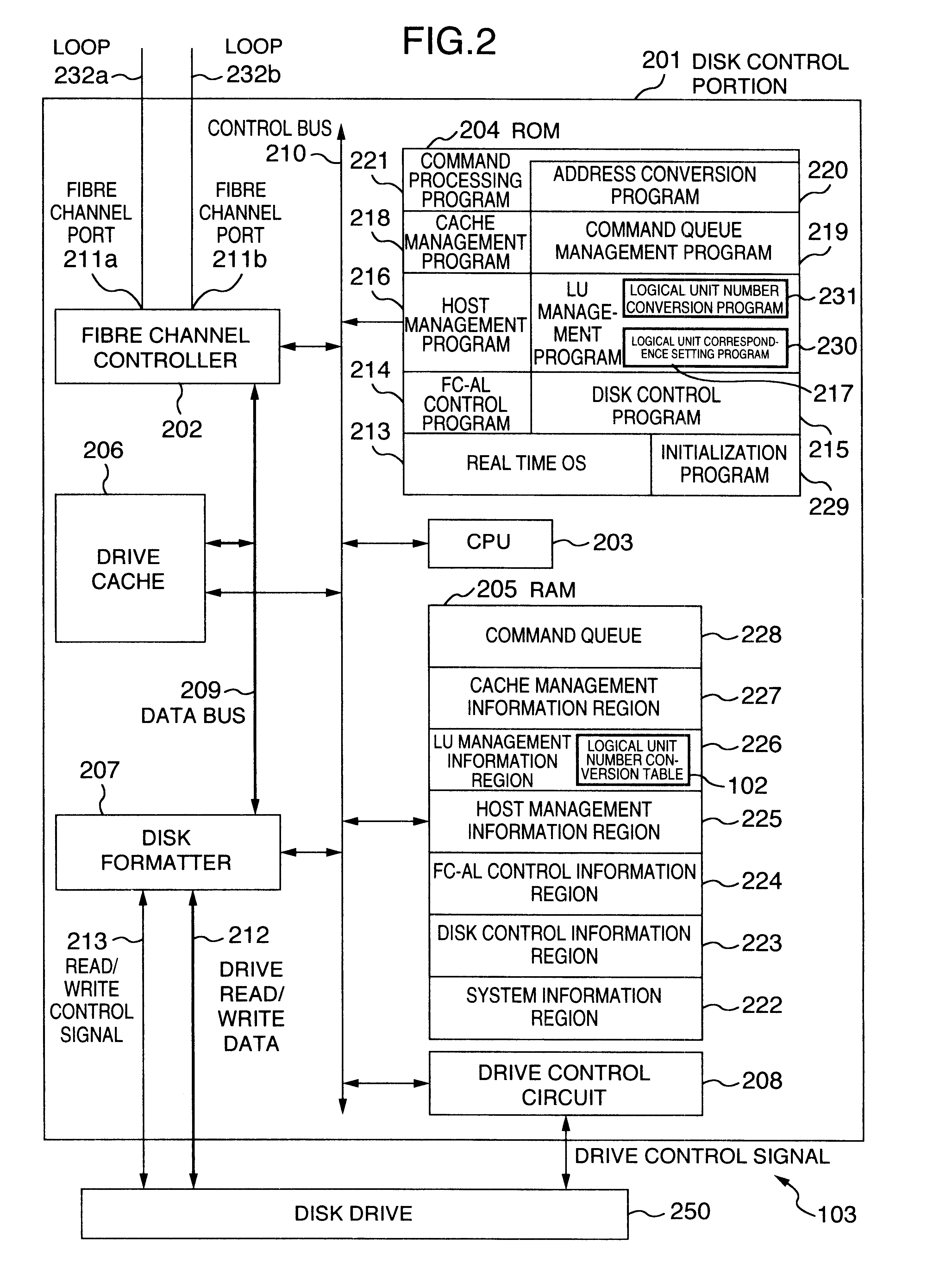
the present invention will be explained with reference to FIGS. 1 to 7. This embodiment represents the application of the present invention to a hard disk drive. FIG. 3 shows a system construction of a computer system comprising host computers and a disk storage apparatus according to the present invention. Two host computers 301a and 301b and a disk storage apparatus 103 are connected through a physical interface of a Fibre Channel and a logical interface of an SCSI. Loop topology called "FC-AL" is used for the connection. The SCSI command is transmitted as a frame of FC-AL from either one of the host computers 301a and 301b to the disk storage apparatus 103. Two loops, that is, Loop 232a and Loop 232b, exist between the host computers 301a and 301b and the disk storage apparatus 103. The host computer 301a has two Fibre Channel Ports whose WWN (World-Wide Names) are WWN 302a and WWN 302c. Numerals 302a to 302d are inherent values for identifying the respective Fibre Channel Ports....

second embodiment

the present invention will be explained with reference to FIGS. 3, 8 and 9. The second embodiment represents the application of the present invention to a disk array. The disk storage apparatus 103 shown in FIG. 3 is a disk array in this embodiment. FIG. 8 shows the internal construction of the disk array 103 of the second embodiment of the present invention. The disk array 103 of this embodiment comprises a disk array controller 1001 and seven hard disk drives 1002a, 1002b, 1002c, 1002d, 1002e, 1002f and 1002g. The physical interface between the disk array controller 1001 and the hard disk drives 1002a to 1002g uses the Fibre Channel and their logical interface, the SCSI. The loop topology called "FC-AL" is used for the connection. Four FC-AL loops 1007a, 1007b, 1007c, 1007d are interposed between the disk array controller 1001 and the hard disk drives 1002a to 1002g. The disk array controller 1001 has Fibre Channel Ports 211a and 211b for the connection with the loops 232a and 232...


PUM


Abstract

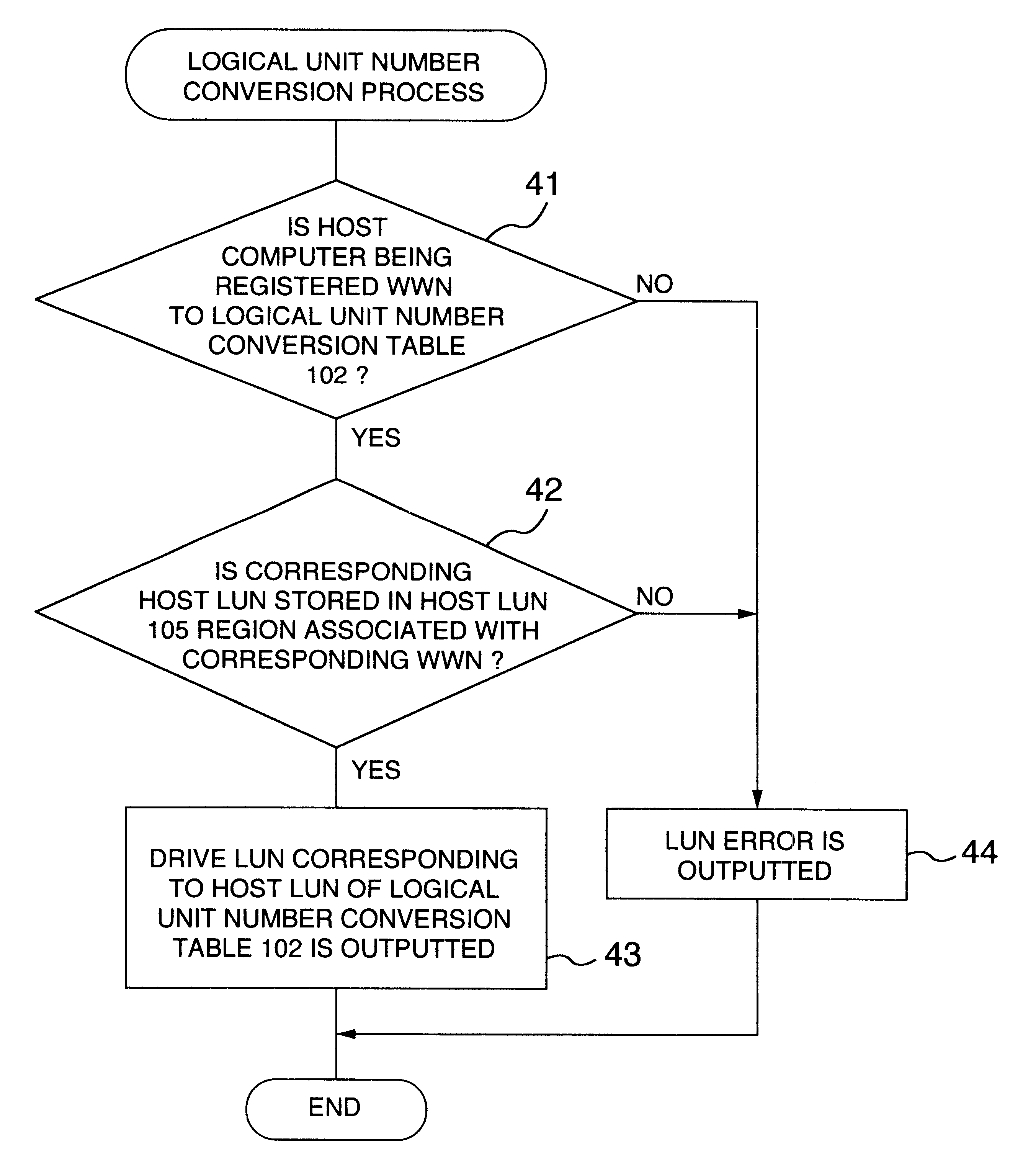
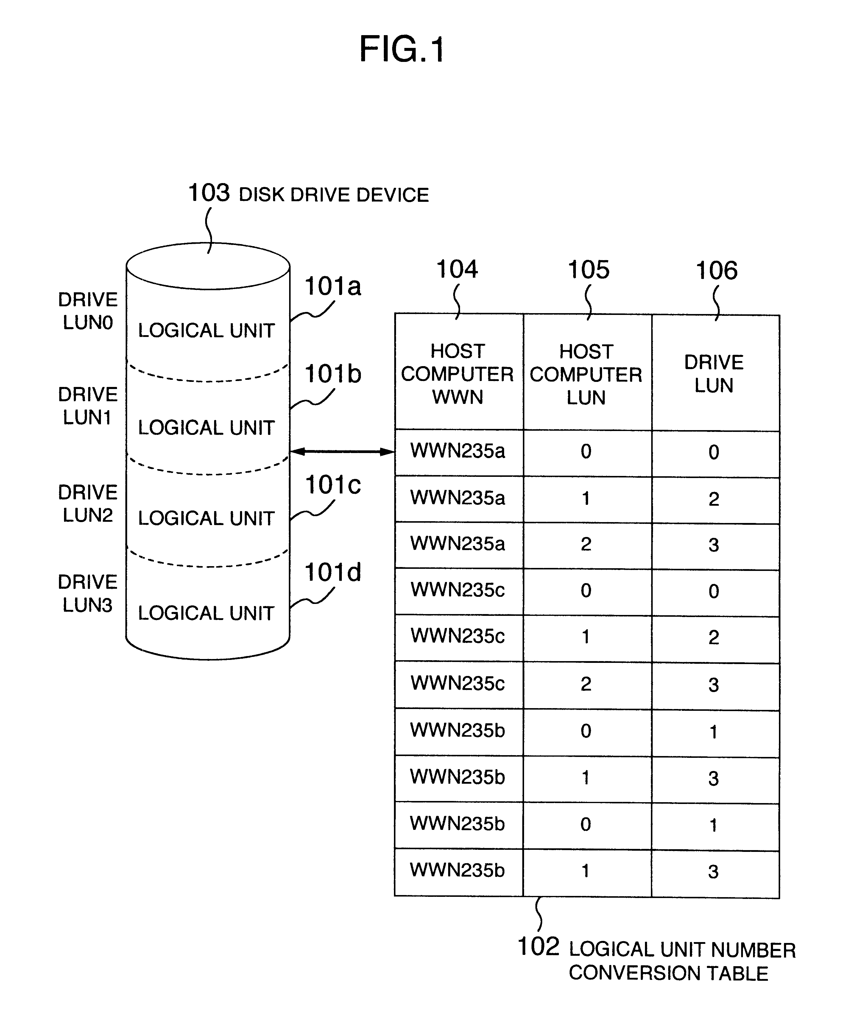
A disk storage apparatus includes a logical unit number correspondence memory for storing the correspondence and the logical unit number designated by a host computer and the logical unit number of the disk storage apparatus, a logical unit number conversion program for converting the logical unit number designated by the host computer to the logical unit number of the disk storage apparatus, and a logical unit correspondence setting program for storing the correspondence of the logical unit number designated by the host computer to the logical unit number of the disk storage in the logical unit number correspondence memory thereby, a plurality of host computers sharing at least one disk storage apparatus.

Description

1. Field of the InventionThis invention relates to a control system of logical units present in a disk storage apparatus, and to a computer system comprising the disk storage apparatus and one or a plurality of host computers.2. Description of the Related ArtA computer system, in which one or a plurality of disk storage apparatuses having a plurality of logical units are connected to a plurality of host computers through high-speed interfaces such as a Fibre Channel and these host computers share one or a plurality of disk storage apparatuses, is known. However, there is a strong demand in such a computer system for storing information inherent to each host computer, such as an OS, in the disk storage apparatus having a high-speed interface, such as a Fibre Channel, and shared by a plurality of host computers, rather than in a disk storage apparatus having an ATA (Advanced Technology Attachment) or SCSI (Small Computer System Interface) interface and connected discretely to each hos...

Claims


Application Information

Patent Timeline
Patent Type & Authority Patents(United States)
IPC IPC(8): G06F3/06
CPCG06F3/0613G06F3/0655G06F3/0689
Inventor ICHIKAWA, MASATOSHIHONDA, KIYOSHIMATSUNAMI, NAOTOKAMIMAKI, HIDEKIKUNISAKI, OSAMU
Owner HITACHI GLOBAL STORAGE TECH JAPAN LTD
Learn More